
Single ultrashort laser pulse contrast measuring device

A measuring device, ultra-short laser technology, applied in the direction of instruments, etc., can solve the problems of unable to reflect the detailed information of contrast, reduction of repetition rate, long shooting period and so on

Inactive Publication Date: 2010-06-30
LASER FUSION RES CENT CHINA ACAD OF ENG PHYSICS
View PDF1 Cites 27 Cited by
  • Summary
  • Abstract
  • Description
  • Claims
  • Application Information

AI Technical Summary

Problems solved by technology

[0002] At present, the scanning third-order autocorrelator is mainly used to measure the ultrashort pulse contrast with a repetition frequency above 10Hz and stable energy output. However, when the pulse is amplified to the Joule level and the intensity reaches the PW level, the shooting cycle is long and the repetition rate will decrease. Reduced to a single shot, for such a single-run ultra-powerful laser device, the scanning method cannot be used, and a single-shot real-time measurement must be used
The Chinese utility model patent (patent number: ZL200720077677) named "High Power Ultrashort Laser Pulse Contrast Measurement Device" can measure the contrast of a single ultrashort laser pulse, which divides the doubled frequency light into several beams with a certain time delay and weakened intensity The doubled frequency light and the fundamental frequency light enter the BBO mixing crystal through a convex lens in parallel to generate a third-order autocorrelation signal, so the third-order autocorrelation signal tested can only be a few discrete points, and cannot reflect the detailed information of the contrast

Method used


Image

  • Single ultrashort laser pulse contrast measuring device
  • Single ultrashort laser pulse contrast measuring device

Examples


Embodiment Construction

[0011] The present invention will be further described below in conjunction with the drawings.

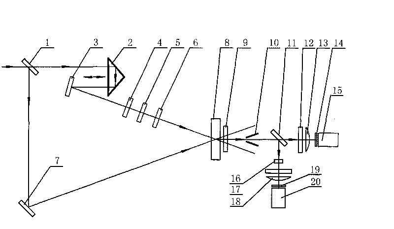
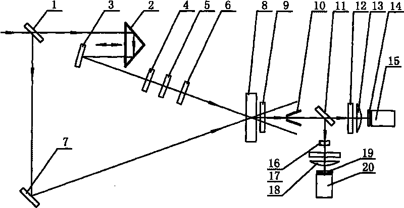
[0012] figure 1 In the device of the present invention, the measured parallel laser beam with a wavelength of 1064 nm and a horizontal polarization state is incident on the first half mirror 1, and the half mirror 1 changes the incident light into transmitted light and reflected light. The transmitted parallel laser beam to be measured first passes through a right-angle prism 2 as an optical delay adjustable device. The function of the right-angle prism 2 is to ensure that the transmitted light and reflected light divided by the half mirror 1 reach the sum frequency crystal 8 through different paths. The previous optical paths are equal, and the light emitted by the right-angle prism 2 enters the first mirror 3 and the type I matching KDP frequency doubling crystal 4 to produce double frequency light with a wavelength of 532 nm. The double frequency light uses the first filter The pl...


PUM


Abstract

The invention provides a single ultrashort laser pulse contrast measuring device. The optical path of the device is described as follows: the measured parallel laser beam passes through a first half-transparent half mirror and is changed into transmission light and reflection light; the transmission light sequentially passes through a right-angle prism, a first reflector, a second-harmonic crystal, an optical filter and a half-wave plate; the reflection light passes through the second reflector; two beams of light enter to a sum-frequency crystal at a phase matching angle to generate three-order self-relation signals which are filtered by a first filter plate and a knife edge; the light is divided into two beams by a second half-transparent half mirror, wherein one beam of light sequentially passes through a first attenuation plate, a first cylindrical lens and a second filter plate and then enters a first CCD (Charge Coupled Device), and the other beam of light sequentially passes through a barrier plate, a second attenuation plate, a second cylindrical lens and a third filter plate and then enters a second CCD; and both CCDs test a main peak where the three-order self-relation signals are located and the area out of the main peak. The invention can obtain continuous relevant signal intensity distribution information and the single ultrashort laser pulse contrast tested by the device can be about 106.

Description

Technical field [0001] The invention belongs to the field of ultrashort pulse testing, and mainly relates to a single shot ultrashort laser pulse contrast measurement device. Background technique [0002] At present, measuring the contrast of ultra-short pulses with a repetition frequency above 10 Hz and stable energy output mainly uses a scanning three-order autocorrelator, but when the pulse is amplified to the Joule level and the intensity reaches the PW level, the target cycle is long and the repetition rate will be Reduced to a single shot. For such a single-shot super laser device, the scanning method cannot be used, and a single shot real-time measurement must be used. The Chinese utility model patent (patent number: ZL200720077677) named "high-power ultrashort laser pulse contrast measurement device" can measure the contrast of a single ultrashort laser pulse, which divides the frequency doubled light into several beams with a certain time delay and weakened intensity Th...

Claims


Application Information

Patent Timeline
IPC IPC(8): G01J11/00
Inventor 孙志红夏彦文傅学军王芳刘华徐隆波彭志涛
Owner LASER FUSION RES CENT CHINA ACAD OF ENG PHYSICS
Learn More