Back projection splicing display screen

A rear projection and display technology, which is applied in the field of rear projection splicing display screens, can solve problems such as image fragmentation and affect the overall effect of the image, and achieve the effect of reducing splicing gaps

Inactive Publication Date: 2010-06-30
GUANGDONG VTRON TECH CO LTD
View PDF1 Cites 9 Cited by
  • Summary
  • Abstract
  • Description
  • Claims
  • Application Information

AI Technical Summary

Problems solved by technology

The screens 1 of each rear projection unit in this splicing structure are independent of each other. Due to reasons such as installation and fixing, thermal expansion and contraction, there is a splicing gap between the screens 1 of two

Method used


Image

  • Back projection splicing display screen
  • Back projection splicing display screen
  • Back projection splicing display screen

Examples


Embodiment 1

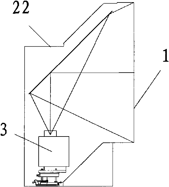
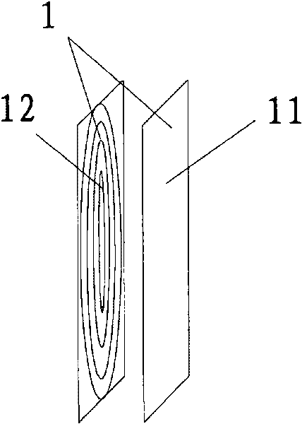
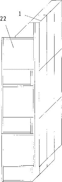
[0017] This example Figure 4 , the seamless rear projection splicing display screen is composed of 3×3 rear projection cabinets 2 spliced ​​with each other, and each rear projection cabinet 2 includes a lens 12 for reversing the rear projection light, and also includes a rear projector and a The box body 22 in which the lens 12 is fixedly installed. For the convenience of adjustment, each rear projection cabinet 2 may also include an adjustment bracket for adjusting the light emitted by the rear projector. On the fronts of 3×3 rear projection cabinets 2 that are spliced ​​together, a whole piece of curtain plate 11 is installed, and this whole piece of curtain plate 11 is close to the lens 12 fronts of 3×3 rear projection cabinets 2 that are spliced ​​with each other. The seamless rear projection splicing display after installation is as follows Figure 5 shown.

[0018] Since a complete curtain panel 11 is used to correspond to multiple spliced ​​rear projection cabinets ...

Embodiment 2

[0020] For larger display screens, it is difficult to use a complete screen panel 11, and the screen panel 11 can be made into a banner shape, such as Figure 6 , 7 As shown, three banner-shaped curtain panels 11 are spliced ​​together, and each curtain panel 11 corresponds to three mutually spliced ​​rear projection cabinets 2 . In this case, although there are splicing gaps between the individual screen panels 11, because one screen panel 11 is used to correspond to the three rear projection cabinets 2 that are spliced ​​together, only three panels are used for the entire rear projection splicing display screen. Banner-shaped curtain panel 11, with figure 2 The number of seams is also greatly reduced compared to where there are only horizontal or vertical seams.

[0021] The above two examples:

[0022] The lens 12 generally refers to a threaded lens 12 , or is also called a Fresnel lens 12 .

[0023] The curtain plate 11 can be a simple scattering curtain, or an optica...


PUM


Abstract

The invention provides a back projection splicing display screen which has no or less screens (1) and is arranged for displaying back projection. The back projection splicing display screen comprises a plurality of spliced back projection cabinets (2) and one or more screen panel (11), wherein the back projection cabinet (2) comprises a box (22) arranged for placing a back projector and a lens (12) fixedly arranged on the front side of the box (22) and each screen panel (11) is arranged on the front side of the lens (12) of the spliced back projection cabinets (2).

Description

technical field [0001] The invention relates to a rear projection splicing display screen. Background technique [0002] The principle of rear projection display is as follows: figure 1 , the rear projector 3 is arranged on the back of the screen 1, and the rear projection light emitted by the rear projector 3 passes through the screen 1 and is emitted from the front of the screen 1 to display images on the screen 1 for viewing. In occasions where images need to be displayed on a large screen, a rear projector 3 can be used to project onto a large-size rear projection screen 1, for example, a rear projector 3 with an output brightness of up to 10,000 lumens can be projected onto a 200-inch large screen A 200-inch large-screen display can be realized. However, this single rear projection display technology is limited by the resolution that can be achieved by a single rear projector 3, so that the projected image pixels are larger and the picture appears rough, which is only...

Claims


Application Information

Patent Timeline
IPC IPC(8): G03B21/62H04N5/74G03B21/625
Inventor 孟凡华
Owner GUANGDONG VTRON TECH CO LTD
Why Eureka
Try Eureka