
Assembly type wall body and mounting method thereof

A prefabricated and wall-mounted technology, which is applied to walls, building components, buildings, etc., can solve the problems of installation error, uneven size of wall panel splicing gaps, etc., and achieve the effect of convenient and quick installation, reduced splicing gaps, and easy removal

Active Publication Date: 2018-12-14
广东爱特仕建材有限公司
View PDF4 Cites 1 Cited by
  • Summary
  • Abstract
  • Description
  • Claims
  • Application Information

AI Technical Summary

Problems solved by technology

With the country's vigorous promotion of prefabricated housing and the continuous advancement of the modernization process, light steel structure engineering will surely develop rapidly, and more and more modern buildings will rise from the ground, so different types of wall structures are formed, but , when the existing light steel wall structure installs the wall panels, the wall panels are generally fixed on the keel by means of nails or screws, and these fixing methods often leave nail holes or screw holes on the surface of the wall panels. In order to ensure the flatness of the outside of the wallboard, it is necessary to cover the surface of the wallboard with fan dust, paint or wallpaper, and in the process of splicing the wallboards, the inevitable installation errors will lead to uneven splicing gaps between the wallboards

Method used


Image

  • Assembly type wall body and mounting method thereof
  • Assembly type wall body and mounting method thereof
  • Assembly type wall body and mounting method thereof

Examples


Embodiment Construction

[0052] The following will clearly and completely describe the technical solutions in the embodiments of the present invention with reference to the accompanying drawings in the embodiments of the present invention. Obviously, the described embodiments are only some, not all, embodiments of the present invention. Based on the embodiments of the present invention, all other embodiments obtained by persons of ordinary skill in the art without creative efforts fall within the protection scope of the present invention.

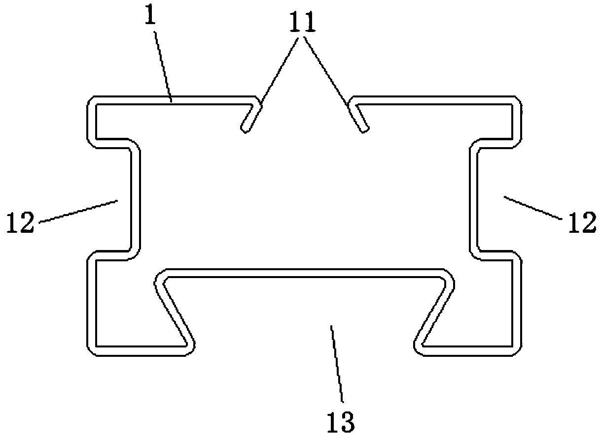
[0053] Such as Figure 1 to Figure 8 As shown, the preferred embodiment of a prefabricated wall provided by the present invention includes a special-shaped keel 1, an inner wall panel 2, an outer wall panel 3 at the beginning, an outer wall panel 4 in the middle and an outer wall panel 5 at the end. At least two keels 1 are arranged at intervals in the length direction of the wall, and a wall unit installation area 6 is formed between the adjacently spaced special-...


PUM


Abstract

The invention discloses an assembly type wall body and a mounting method thereof. The assembly type wall body comprises a special-shaped keel, an inner wall board, a starting outer wall board, a middle outer wall board and an ending outer wall board; a first buckling position is formed at the front side of the special-shaped keel; second buckling positions are formed at the left side and right side of the special-shaped keel respectively; two sides of the back surface of the inner wall board are respectively provided with inner wall buckles buckled to the second buckling positions; two sides othe back surface of the starting outer wall board are respectively provided with first outer wall buckling edges which are buckled to the first buckling position; two sides of the back surface of themiddle outer wall board are respectively provided with second outer wall buckling edges which are buckled to the outer sides of the first outer wall buckling edges, the outer sides of second outer wall buckling edges or the first buckling position; and two sides of the back surface of the ending outer wall board are respectively provided with outer clamping buckles which are buckled to the outersides of the first outer wall buckling edges, the outer sides of the second outer wall buckling edges or the first buckling position. The invention also discloses a mounting method applied to the assembly type wall body. With the mounting method adopted, the mounting mode of the wall body is more convenient and quicker; the wall body is easy to remove; and the structure of the wall body can be flatter and more compact.

Description

technical field [0001] The invention belongs to the technical field of light steel buildings, and more specifically relates to a prefabricated wall and an installation method thereof. Background technique [0002] Light steel structure building is a very vital steel structure system, which has been widely used in general industrial and agricultural, commercial, and service buildings, such as office buildings, villas, warehouses, stadiums, entertainment, tourist buildings, and low and multi-storey residential buildings, etc. In the field of construction, light steel structures are not only light in structural materials, but also use light heat preservation and fireproof materials in their enclosure materials. With the country's vigorous promotion of prefabricated houses and the continuous advancement of the modernization process, light steel structure engineering will surely develop rapidly, and more and more modern buildings will rise from the ground, so different types of w...

Claims


Application Information

Patent Timeline
Patent Type & Authority Applications(China)
IPC IPC(8): E04B2/74
CPCE04B2/74E04B2/7407E04B2/7433E04B2002/7461
Inventor 高守岗
Owner 广东爱特仕建材有限公司
Learn More