Direct-injection sprue type passive needle valve

A passive, needle valve technology, applied to the needle valve field in the injection molding field, can solve the problems of long maintenance time, poor color changeability of the needle valve, and clean flushing, shortening maintenance time, simplifying loading and unloading, and reducing flow resistance. Effect

Inactive Publication Date: 2016-09-14
高建鸣
View PDF8 Cites 2 Cited by
  • Summary
  • Abstract
  • Description
  • Claims
  • Application Information

AI Technical Summary

Problems solved by technology

At present, there are some deficiencies in the use of the existing direct-gate passive needle valves, and it is difficult to make the direct-gate passive needle valves widely used.
The disadvantage of the existing technical solution is mainly that the runner in the needle valve is spliced ​​by different parts, and the error of processing and assembly causes the corners and gaps of the runner to stagnate at the splicing place, which makes it difficult for injection molding the same product with different colors. The problem is that the stagnant material in the needle valve runner is difficult to be washed away by another color of melt, that is, the so-called "color change" of the needle valve is poor.
[0003] In addition, the needle valve is one of the core technologies in the hot runner system, the cost of after-sales technical services is relatively high, and the time required for maintenance is relatively long

Method used


Image

  • Direct-injection sprue type passive needle valve
  • Direct-injection sprue type passive needle valve
  • Direct-injection sprue type passive needle valve

Examples


Embodiment Construction

[0029] Below in conjunction with accompanying drawing and specific embodiment the present invention is described in further detail:

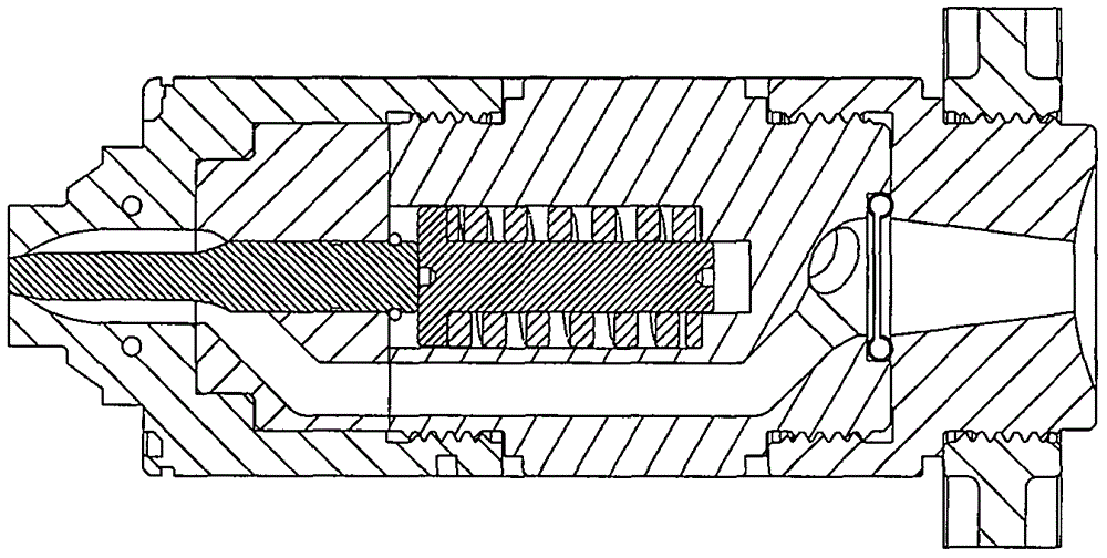
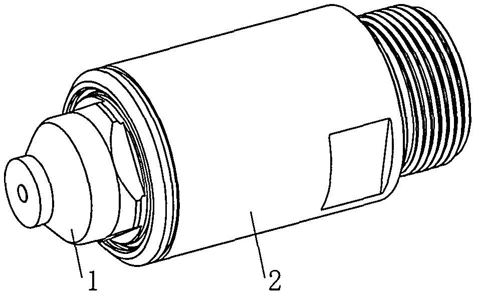
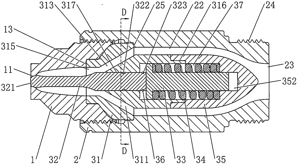
[0030] see Figure 2 ~ Figure 11 , the direct shot gate passive needle valve of the present invention includes a valve nozzle 1 , a valve body 2 and a valve core 3 . The small end of the valve nozzle 1 is provided with a tapered central injection port 11 . The center of the valve body 2 is provided with a through hole that smoothly transitions from the large hole 22 to the small hole 23, and one end of the valve body 2 is also provided with a cavity structure 21 with an internal thread and communicates with the large hole 22 of the through hole. , The outer wall of the other end of the valve body 2 is provided with an external thread 24, which can be connected to a flange or a sleeve so as to increase the length of the needle valve. The valve core 3 is composed of a valve core body 31, a valve needle 32, a push rod 33, a spring 34, a valve cor...


PUM


Abstract

A direct-injection sprue type passive needle valve comprises a valve mouth, a valve body and a valve core. The valve core is majorly composed of a valve core body, a valve needle, a push rod, a spring and a valve core lid. At least two sub-runners are evenly distributed on the valve core in the circumferential direction. A stepped through hole is formed in the center of the valve core body. A stepped hole is formed in the center of the valve core lid. The stepped hole of the valve core lid and the stepped through hole of the valve core body are jointed in a butt joint mode to form a cavity. The push rod and the spring are arranged inside the cavity. The valve needle is arranged in the stepped through hole of the valve core body. The valve mouth is arranged at one end, close to the valve needle, of the valve core in a sleeving mode. The other end of the valve core is sleeved with the valve body. A passageway is formed from a small hole end of the valve body to a center ejection opening of the valve mouth. According to the direct-ejection sprue type passive needle valve, the flow resistance inside the sub-runners in the needle valve is reduced, the color changing property of the passive needle valve is improved, the difficulty of assembling and maintenance is reduced, the maintenance time period is shortened, and the cost of after-sales service is reduced.

Description

technical field [0001] The invention relates to a needle valve, in particular to a needle valve used in the field of injection molding. Background technique [0002] The passive needle valve using a spring as an energy storage element is a very distinctive needle valve, which has the characteristics of compact structure, relatively low manufacturing cost and easy assembly and disassembly, and has been used in the injection molding industry for decades. At present, there are some deficiencies in the use of the existing direct-injection gate passive needle valves, and it is difficult to make the direct-injection gate passive needle valves widely used. The disadvantage of the existing technical solution is mainly that the runner in the needle valve is spliced ​​by different parts, and the error of processing and assembly causes the corners and gaps of the runner to stagnate at the splicing place, which makes it difficult for injection molding the same product with different col...

Claims


Application Information

Patent Timeline
Patent Type & Authority Applications(China)
IPC IPC(8): F16K1/38F16K27/02
CPCF16K1/38F16K27/0254
Inventor 高建鸣
Owner 高建鸣
Why Eureka
Try Eureka