Method and system for braking magnetizing inrush current in differential protection of ultra-high voltage transformer

A technology of excitation inrush current and differential protection, applied in the direction of emergency protection circuit devices, electrical components, etc., can solve problems such as differential protection misoperation, differential protection refusal, three-phase ratio differential, etc., to achieve accurate and reliable operation, Avoid the effect of refusal to move

Active Publication Date: 2010-06-30
BEIJING SIFANG JIBAO AUTOMATION +1
View PDF0 Cites 26 Cited by
  • Summary
  • Abstract
  • Description
  • Claims
  • Application Information

AI Technical Summary

Problems solved by technology

Years of operating experience and tests have shown that there may be a phase with low second harmonic content, so the use of split-phase braking may easily lead to differential protection misoperation
[0009] "OR gate brake" may lead to differential protection refusal or delayed action
For example, when the transformer is closed on an internal single-phase fault, such as a phase A fault; phase B and phase C are non-fault phases, and there may be exciting inrush currents in phase B and phase C, and their second harmonic content is relatively high. Braking, therefore, will block the three-phase ratio differenti...

Method used


Image

  • Method and system for braking magnetizing inrush current in differential protection of ultra-high voltage transformer
  • Method and system for braking magnetizing inrush current in differential protection of ultra-high voltage transformer
  • Method and system for braking magnetizing inrush current in differential protection of ultra-high voltage transformer

Examples


Embodiment Construction

[0041] In order to make the above objects, features and advantages of the present invention more comprehensible, specific implementations of the present invention will be described in detail below in conjunction with the accompanying drawings.

[0042] In order to enable those skilled in the art to implement the present invention better, several basic concepts are introduced first.

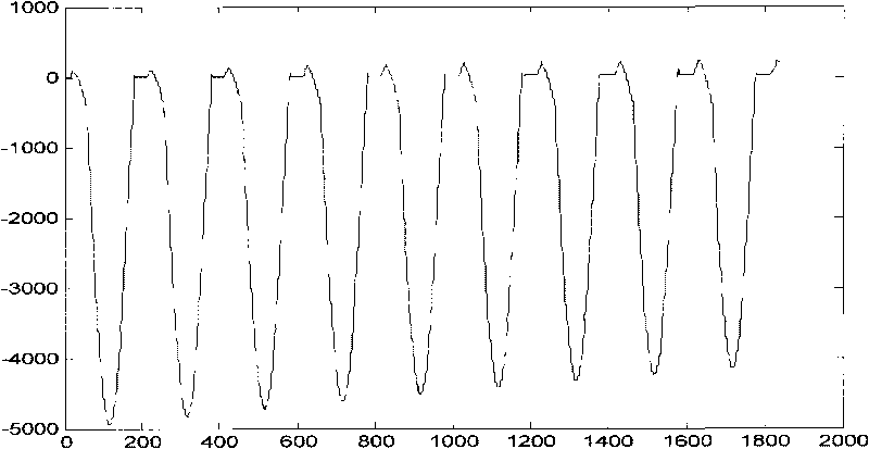
[0043] see figure 1 , which is a typical excitation inrush current waveform of a transformer.

[0044] From figure 1 Several characteristic quantities can be seen in: amplitude offset, harmonics and waveform discontinuity.

[0045] where the amplitude offset can be given by figure 1 Most of the medium waveforms are seen on the negative half axis of the vertical axis, rather than being evenly distributed on the positive and negative half axes. Harmonics can be seen from the peaks of the waveform. The ideal peaks should be arc-shaped with a smooth transition, but the current peaks appear flatten...


PUM


Abstract

The invention provides a method for braking a magnetizing inrush current in the differential protection of an ultra-high voltage transformer, which comprises the following steps: acquiring a corresponding magnetizing inrush current criterion of each phase by the weight of an amplitude bias current, the weight of a secondary harmonic current and a symmetry degree of the waveform of each phase; and braking the magnetizing inrush currents of the phases whose magnetizing inrush current criterions are greater than a magnetizing inrush current braking coefficient. The method provided by the invention comprehensively considers the sizes of the three parameters, i.e. the weight of the amplitude bias current, the weight of the secondary harmonic current and the symmetry degree of the waveform. The increase or decrease of only one of the parameters cannot determine whether the whole magnetizing inrush current criterion is greater than or less than the magnetizing inrush current braking coefficient so as to solve the defect of only utilizing the secondary harmonic as the magnetizing inrush current criterion in the prior art. The invention makes the braking of the magnetizing inrush current more reliable so as to have a more accurate tripping of the differential protection of the transformer without causing false tripping or refuse operation. The invention also provides a system for braking the magnetizing inrush current in the differential protection of the ultra-high voltage transformer.

Description

technical field [0001] The invention relates to the technical field of UHV transformers, in particular to a method and system for braking inrush current in UHV transformer differential protection. Background technique [0002] At present, the differential protection of transformers mainly solves two problems in practice: one is to identify the inrush current and fault current; the other is to distinguish external faults from internal faults. Differential protection of transformers can better distinguish external faults and internal faults to a certain extent, but there are still some deficiencies in the identification of inrush current and fault current. [0003] At present, the current waveform is mainly used as the main basis for judging the excitation inrush current and fault current. Among various excitation inrush braking schemes, the second harmonic braking is relatively mature and reliable. The protection of main transformers at home and abroad is basically equipped...

Claims


Application Information

Patent Timeline
IPC IPC(8): H02H7/045
Inventor 韩先才刘洪涛肖远清聂娟红屠黎明刘建飞
Owner BEIJING SIFANG JIBAO AUTOMATION
Why Eureka
Try Eureka