Hand and electric clutch unit for change-over switch

A clutch device, transfer switch technology, applied in electrical switches, circuits, electrical components and other directions, can solve problems such as large resistance torque and laborious operation

Inactive Publication Date: 2003-11-05
SUZHOU FUTURE ELECTRICAL APP
View PDF0 Cites 8 Cited by
  • Summary
  • Abstract
  • Description
  • Claims
  • Application Information

AI Technical Summary

Problems solved by technology

Since the output shaft of the deceleration mechanism is the active one, which in turn drives the speed-up transmis...

Method used


Image

  • Hand and electric clutch unit for change-over switch
  • Hand and electric clutch unit for change-over switch
  • Hand and electric clutch unit for change-over switch

Examples


Embodiment 1

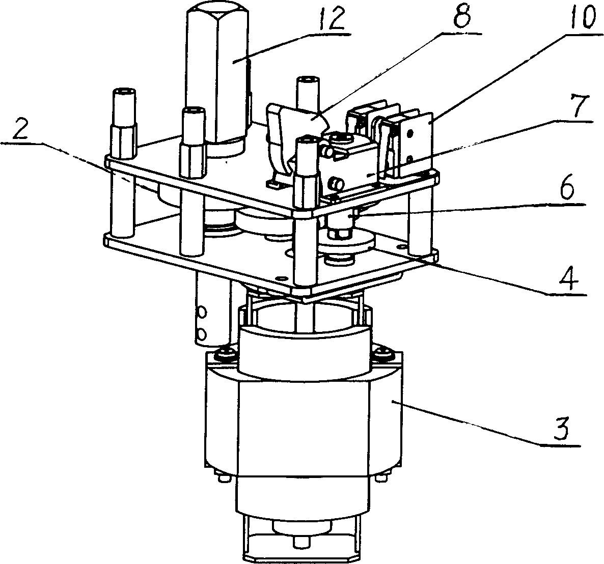
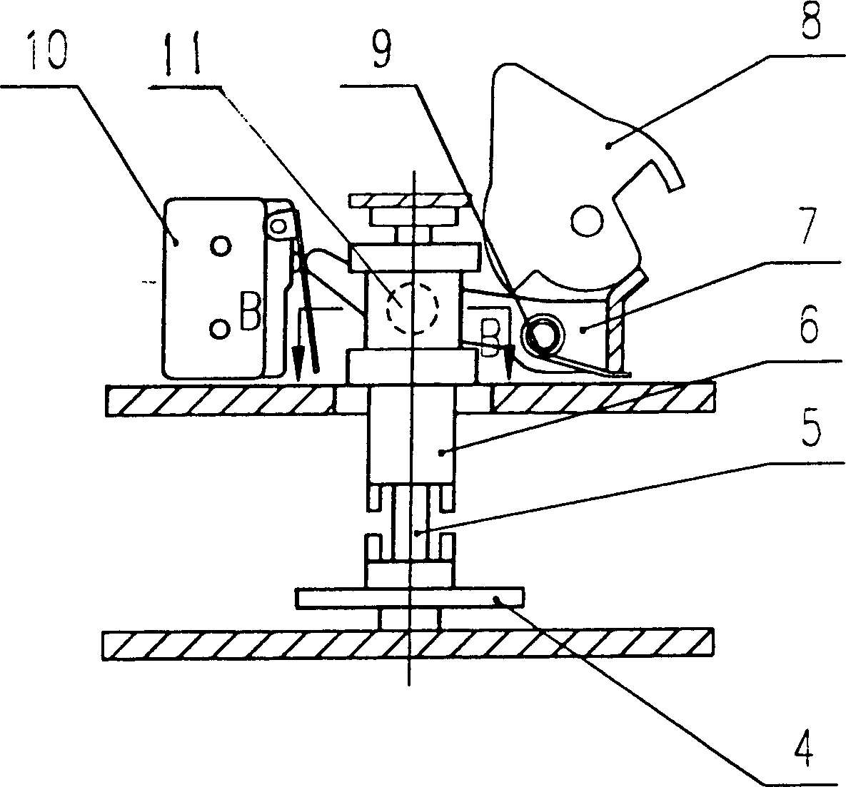
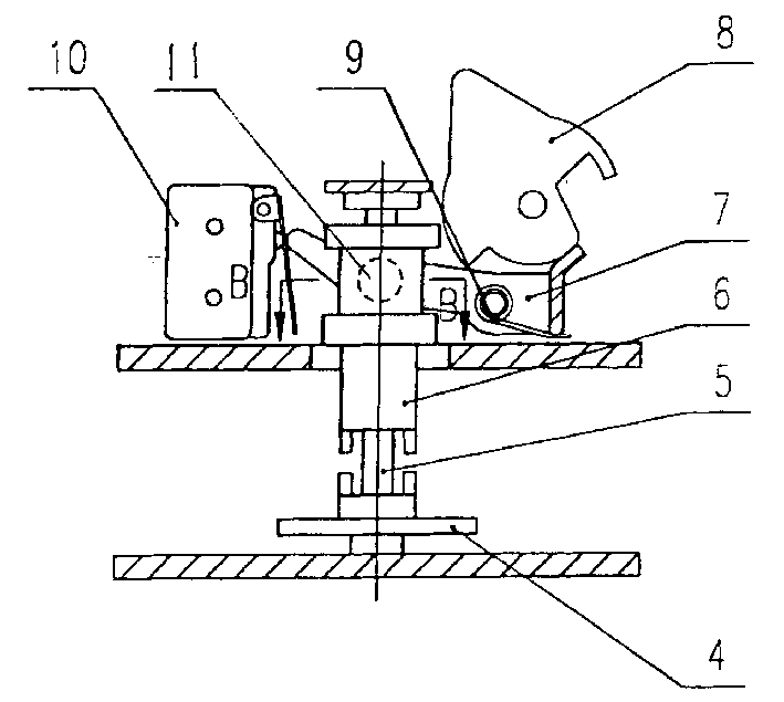
[0012] The manual electric clutch device used in the transfer switch in this embodiment is mainly composed of a drive motor 3, a five-stage gear reduction mechanism 2, an actuator (not shown in the figure) and a clutch mechanism. The main shaft pinion of the drive motor 3 meshes with the bull gear 4 in the gear reduction mechanism, and then meshes with the next-stage bull gear through the pinion 6 coaxial with the bull gear 4 until it passes through the five-stage gear deceleration mechanism 2, and finally by The handle shaft 12 is connected with the actuator as an output. The handle shaft 12 upper end is made into a square tenon shape, which can be inserted into the handle when needed.

[0013] The clutch mechanism is mainly composed of a common shaft 5, a fork 7, a shift handle 8 and a short shaft 11. The pinion 6 is looped on the common shaft 5 at the center of the bull gear 4. The opposite ends of the pinion 6 and the bull gear 4 are provided with end teeth. Return torsi...


PUM


Abstract

The hand and electric clutch unit for change-over switch consists of drive motor, reducing mechanism, executing mechanism and handle. It also has clutch mechanism and micro switch connected seriallywith the drive motor. The clutch mechanism is installed inside the drive link of the reducing mechanism and has clutching control part installed near the output shaft of the reducing mechanism and with one end pushing against the micro switch to constitute electromechanical interlocking structure. In the hand switching of power supply, the clutching control part is pushed to separate the outputshaft of the reducing mechanism from the drive motor and turn off the micro switch. Pushing the handle drives the executing mechanism only without driving the motor owing to the cut-off power supplyfor the drive motor.

Description

technical field [0001] The invention relates to a dual-power transfer switch (also known as a double-throw switch) capable of switching to a backup power supply when the main power supply fails, in particular to a manual electric clutch device for the transfer switch, which belongs to the technical field of power switches . Background technique [0002] Hospitals, high-end hotels and other important places that need to ensure uninterrupted power supply are usually equipped with transfer switches. The switch is connected with main power supply and backup power supply. When the main power supply fails, the transfer switch can be manually or automatically switched to the backup power supply. The manual electric clutch device that is used for changeover switch in the prior art is mainly made up of drive motor, deceleration mechanism, executive mechanism and handle. Wherein the main shaft of the driving motor is connected with the executive mechanism through the reduction mecha...

Claims


Application Information

Patent Timeline
IPC IPC(8): H01H3/54H01H3/58
Inventor 胡其良楼铭达徐惠兴
Owner SUZHOU FUTURE ELECTRICAL APP
Why Eureka
Try Eureka