Imaging apparatus and its control method

A technology of camera equipment and controller, applied in image communication, TV, color TV, etc., can solve the problems of information error and loss, and achieve the effect of suppressing blur

Inactive Publication Date: 2010-07-14
CANON KK
View PDF2 Cites 12 Cited by
  • Summary
  • Abstract
  • Description
  • Claims
  • Application Information

AI Technical Summary

Problems solved by technology

[0007] However, the information corresponding to the distance to the subject may sometimes contain errors
Information that contains errors may be lost with an increase corresponding to Figure 5 Possibility of consistency of information from the trajectories shown

Method used


Image

  • Imaging apparatus and its control method
  • Imaging apparatus and its control method
  • Imaging apparatus and its control method

Examples


Embodiment Construction

[0020] Various embodiments, features, and aspects of the invention will be described in detail below with reference to the accompanying drawings.

[0021] In the following, the prerequisite technology according to the embodiment of the present invention is explained.

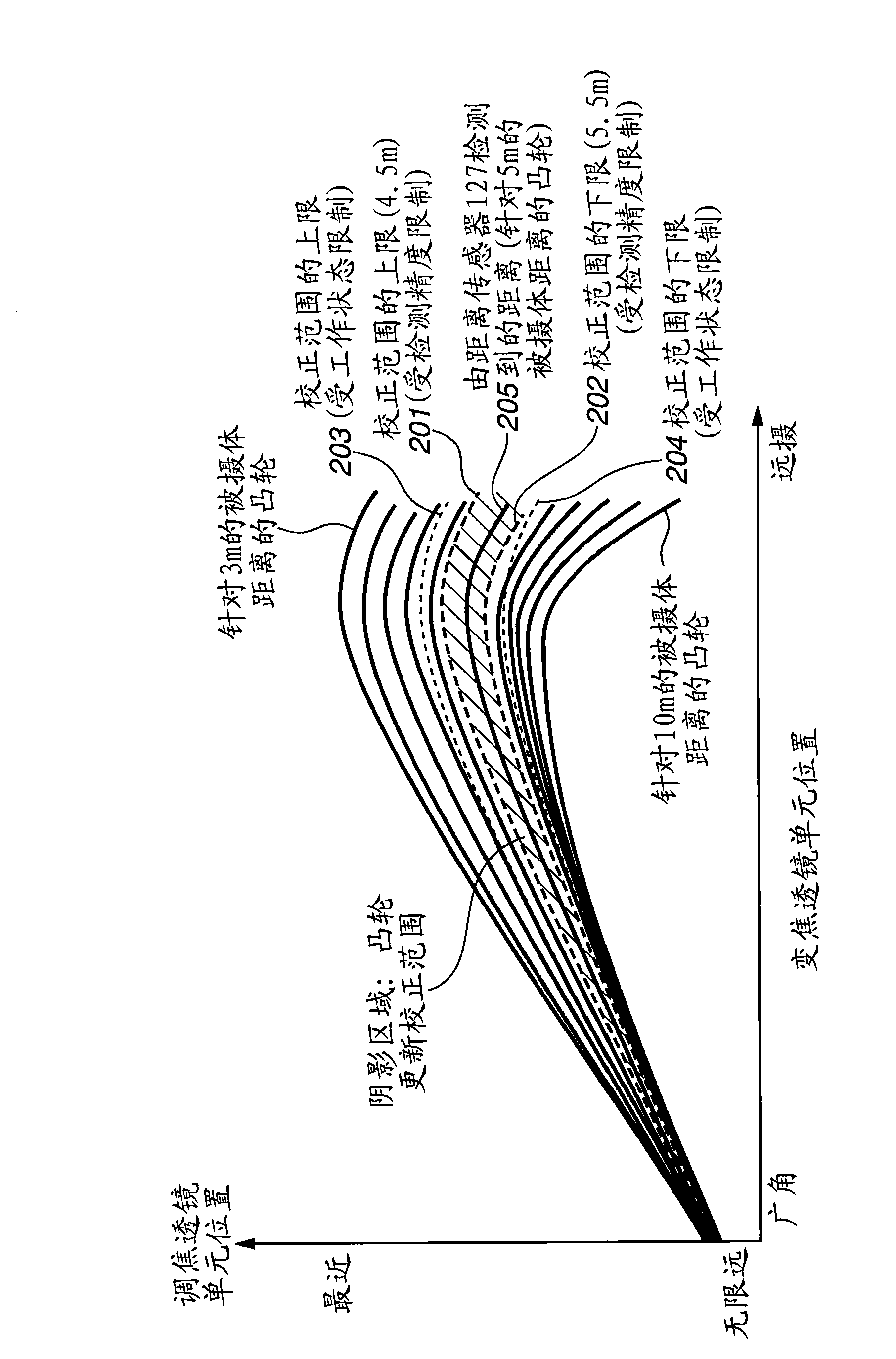
[0022] For example, in the instructions of Japanese Patent Application Laid-Open No. 2005-128107 and Figure 5 In , the trajectory tracking method for the focusing lens unit in the internal focusing type lens system is discussed. In the specification of Japanese Patent Laid-Open No. 2005-128107 and FIG. 10 , an interpolation method in the moving direction of the zoom lens unit is discussed.

[0023] Furthermore, in the specification of Japanese Patent Laid-Open No. 2005-128107 and FIG. 11 , an example of table data of focus track information stored in a microcomputer is discussed.

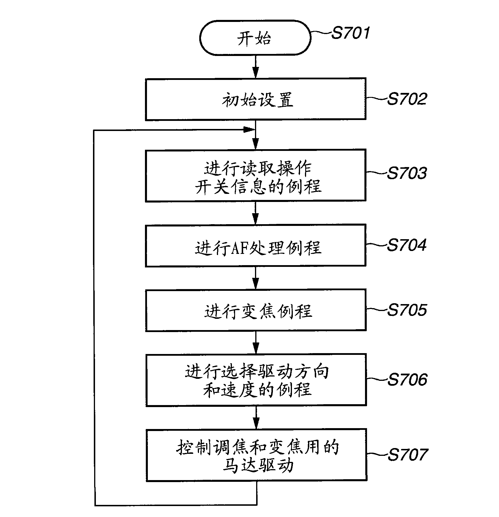
[0024] Typically, zoom control including focus detection using an image signal from an image sensor is performed in synchronizatio...


PUM


Abstract

The invention relates to an imaging apparatus and its control method. The imaging apparatus controls a movement of a second lens unit to compensate for an image-plane movement due to a movement of a first lens unit when a captured image is zoomed by moving the first lens unit, and controls the movement of the second lens unit to be performed within a range selected from data based on second information corresponding to an object distance. The data indicates a position of the first lens unit and a position of the second lens unit on an optical axis located behind the first lens unit, and is provided for each of object distances. The range of the movement of the second lens unit is changed according to a detection result by a second detection unit at a predetermined time.

Description

technical field [0001] The present invention relates to a lens control technique in an imaging device such as a camera. Background technique [0002] In a so-called inner focus type lens system in which the focus lens unit is located behind the zoom lens unit on the optical axis, the Figure 5 Zooming is performed on a track selected from among the displayed plurality of tracks (electronic cam tracks) or information corresponding to these tracks. and Figure 5 The information on or corresponding to the shown plurality of trajectories (electronic cam trajectories) may be information representing the trajectories themselves, or may be functions each having a variable corresponding to the lens position. [0003] When the zoom lens unit moves from the telephoto end to the wide-angle end, due to Figure 5 The plurality of tracks shown converges in one direction from a state where they are spaced apart from each other by some interval, and thus the focused state can be maintained ...

Claims


Application Information

Patent Timeline
Patent Type & Authority Applications(China)
IPC IPC(8): G03B13/36H04N5/232
CPCH04N5/23248H04N5/23296G02B7/282G02B27/646H04N23/68H04N23/69
Inventor 本宫英育
Owner CANON KK
Why Eureka
Try Eureka