Method of controlling electro-optical device, control device for electro-optical device, electro-optical device, and electronic apparatus

a technology of electro-optical devices and control devices, applied in the direction of instruments, computing, electric digital data processing, etc., can solve the problems of difficult suppression of boundary blurring, and achieve the effect of suppressing boundary blurring and high-quality images

Active Publication Date: 2012-10-18
E INK CORPORATION
View PDF13 Cites 7 Cited by
  • Summary
  • Abstract
  • Description
  • Claims
  • Application Information

AI Technical Summary

Benefits of technology

[0007]An advantage of some aspects of the invention is that it provides a method of controlling an electro-optical device, a control device for an electro-optical device, an electro-optical device, and an electronic apparatus capable of suppressing the occurrence of blurring of a boundary of an image displayed in a display section and displaying a high-quality image.

Problems solved by technology

However, according to the technique described in JP-A-2010-113281, while the edge residual image can be erased, there is a technical problem in that it is difficult to suppress the occurrence of blurring of the boundary.

Method used


Image

  • Method of controlling electro-optical device, control device for electro-optical device, electro-optical device, and electronic apparatus
  • Method of controlling electro-optical device, control device for electro-optical device, electro-optical device, and electronic apparatus
  • Method of controlling electro-optical device, control device for electro-optical device, electro-optical device, and electronic apparatus

Examples


first embodiment

[0077]First, an electrophoretic display of a first embodiment will be described with reference to FIGS. 1 to 13.

Apparatus Configuration

[0078]The overall configuration of the electrophoretic display of this embodiment will be described with reference to FIGS. 1 to 2.

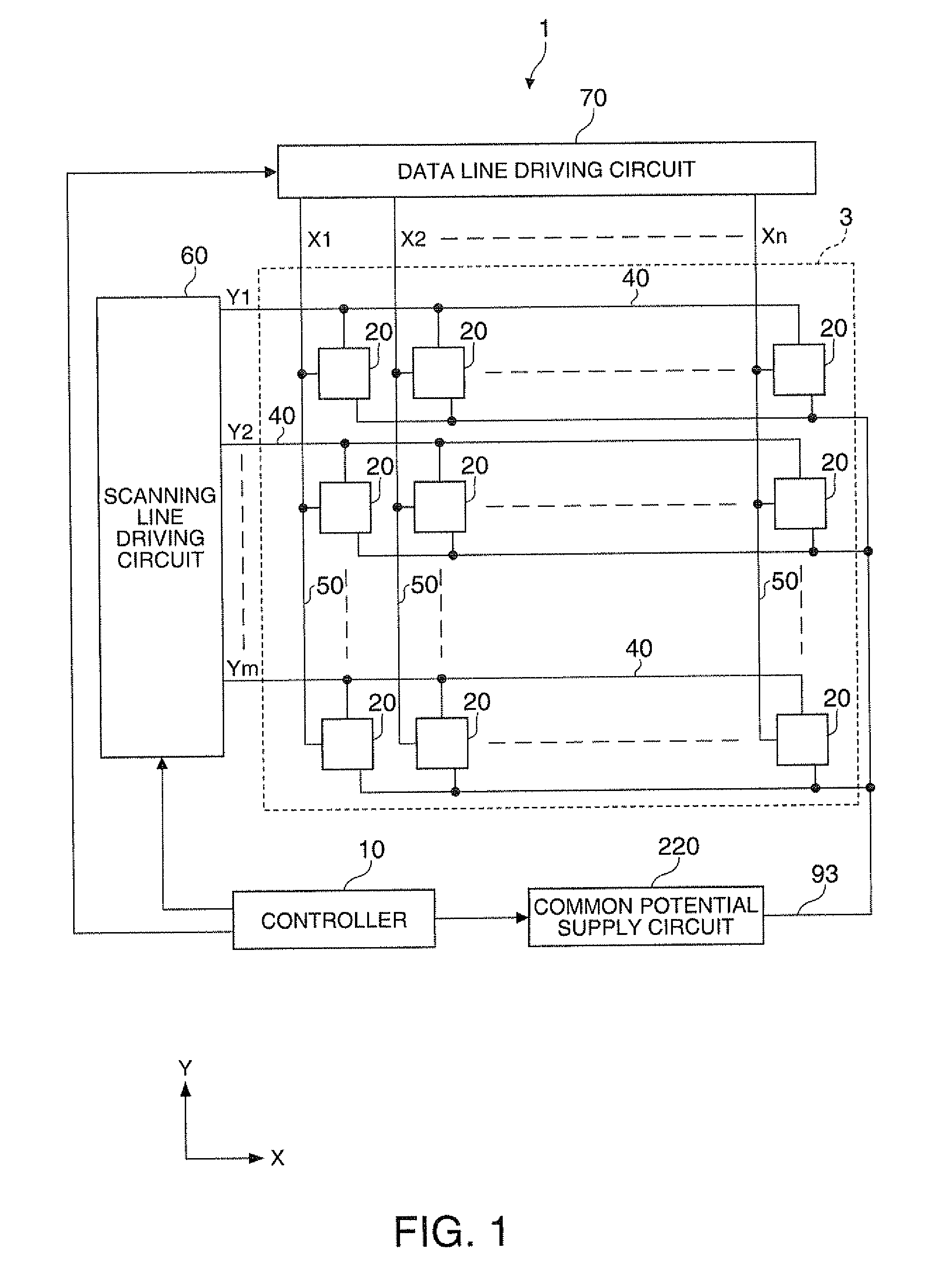
[0079]FIG. 1 is a block diagram showing the overall configuration of the electrophoretic display of this embodiment.

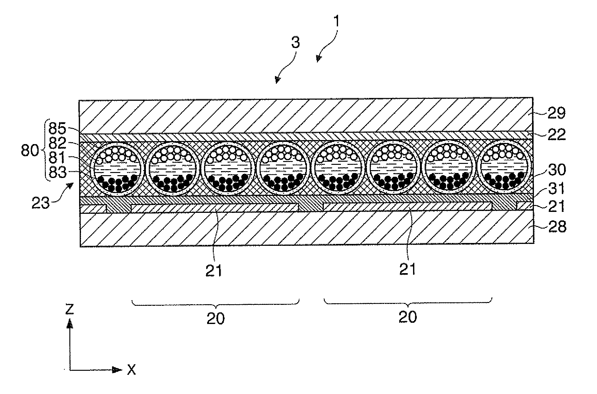
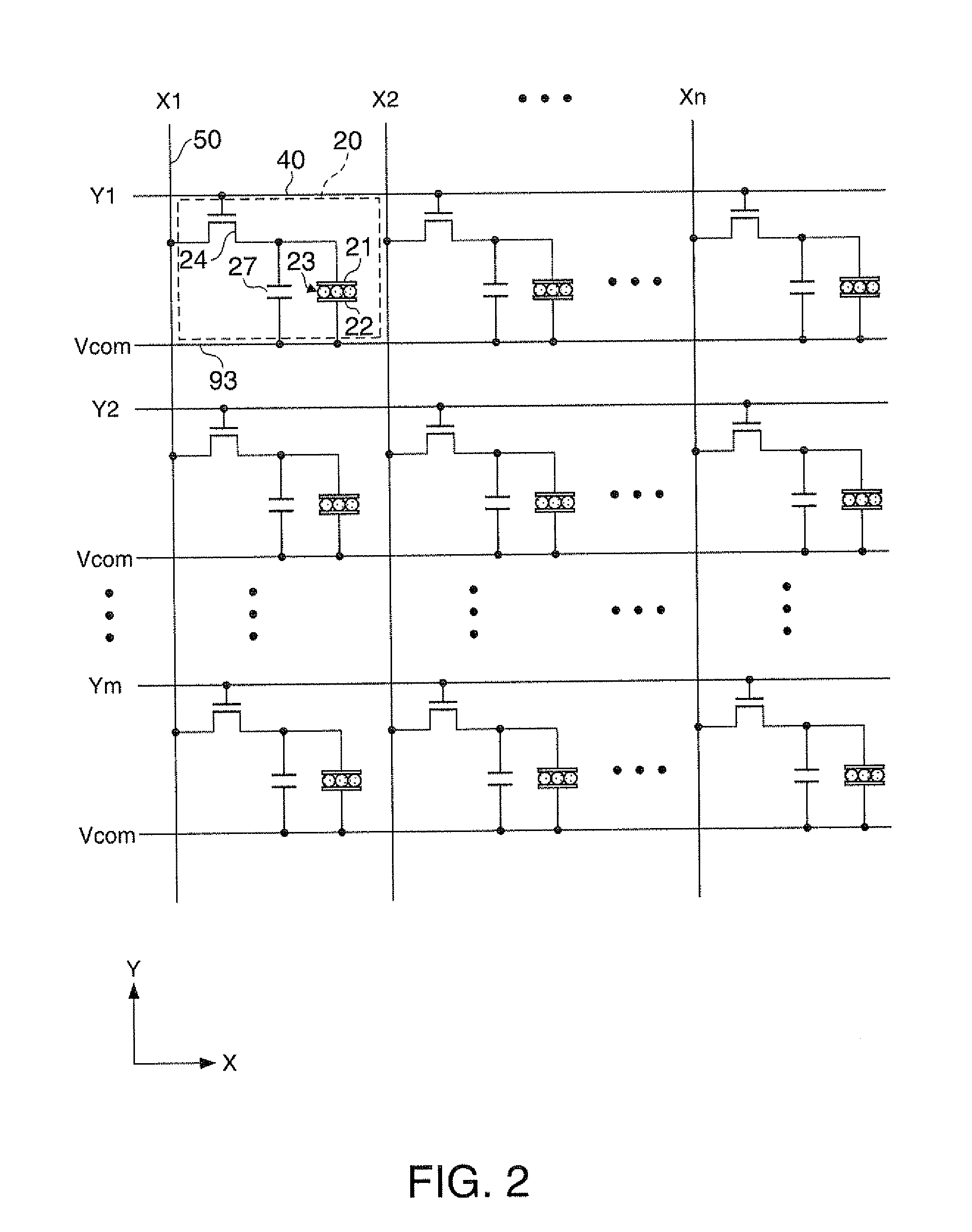
[0080]Referring to FIG. 1, an electrophoretic display 1 of this embodiment is an active matrix driving electrophoretic display, and includes a display section 3, a controller 10, a scanning line driving circuit 60, a data line driving circuit 70, and a common potential supply circuit 220. The controller 10 is an example of “a control device for an electro-optical device” described in the appended claims. The scanning line driving circuit 60 and the data line driving circuit 70 form an example of “a driving section” described in the appended claims.

[0081]The display section 3 has m rows×n columns pixels 20 in...

second embodiment

[0164]Next, a method of controlling a electrophoretic display according to a second embodiment will be described with reference to FIGS. 14 to 17. Hereinafter, as shown in FIG. 14, the method of controlling the electrophoretic display 1 will be described as to an example where an image displayed in the display section 3 is rewritten from an image P1 to an image P2. Each of the images P1 and P2 is a two-gradation image having two gradations of black and white. FIG. 14 is a plan view showing an example of the image P1 before rewriting and the image P2 after rewriting.

[0165]FIG. 15 is a conceptual diagram conceptually showing a method of supplying the data potential to a plurality of pixel electrodes 21 during image rewriting in the electrophoretic display 1. FIG. 15 conceptually shows the data potential, which is supplied to a plurality of pixel electrodes 21 in each of a plurality of frame periods T1, T2, T3, and T4, on the upper side. On the lower side of FIG. 15, an image which is ...


PUM


Abstract

A method of controlling an electro-optical device includes, during image rewriting, executing a first control operation to supply a potential different from a potential on a counter electrode to a pixel electrode of a first pixel in a plurality of frame periods, executing a second control operation to supply the same potential as the potential on the counter electrode to a pixel electrode of a second pixel, which is adjacent to the first pixel and in which a gradation to be displayed during image rewriting is not changed, in at least some frame periods of a plurality of frame periods, and executing a third control operation to supply a potential different from the potential on the counter electrode to the pixel electrode of the second pixel in a frame period after the potential has been supplied in at least one frame period during the first control operation.

Description

BACKGROUND[0001]1. Technical Field[0002]The present invention relates to technical fields of a method of controlling an electro-optical device, such as an electrophoretic display device, a control device for an electro-optical device, an electro-optical device, and an electronic apparatus.[0003]2. Related Art[0004]As an example of this type of electro-optical device, an electrophoretic display is known in which a voltage is applied between a pixel electrode and a counter electrode arranged to be opposite each other with an electrophoretic element including electrophoretic particles interposed therebetween, and the electrophoretic particles, such as black particles and white particles, are moved to display an image in a display section (for example, see Japanese Patent No. 3750565 and JP-A-2010-113281). The electrophoretic element has a plurality of microcapsules each including a plurality of electrophoretic particles, and is fixed between the pixel electrode and the counter electrod...

Claims


Application Information

Patent Timeline
Patent Type & Authority Applications(United States)
IPC IPC(8): G09G5/10
CPCG09G2310/02G09G3/344G09G2310/06
Inventor MUTO, KOTAYAMADA, YUSUKEYAMADA, TOSHIMICHIKANAMORI, HIROAKI
Owner E INK CORPORATION
Why Eureka
Try Eureka