Image generation apparatus

a technology of image generation and apparatus, applied in the field of image generation apparatus, can solve problems such as flicker, and achieve the effects of reduced blurring, suppressing blurring, and high accuracy

Active Publication Date: 2016-11-24
DENSO CORP
View PDF7 Cites 8 Cited by
  • Summary
  • Abstract
  • Description
  • Claims
  • Application Information

AI Technical Summary

Benefits of technology

[0011]As a result of a configuration such as this, a plurality of captured images in which blurring is reduced is generated with a single camera. In addition, after positional misalignment among these captured images is corrected, a composite image of these captured images is generated. Blurring is suppressed in each captured image. Therefore, information illustrated on a display board can be recognized with high accuracy from the composite image. In addition, because images captured using a plurality of imaging operations are combined, luminance distribution can be made suitable for recognition of information displayed on an electronic display apparatus. Therefore, a process based on the information illustrated on the display board and the information displayed on the electronic display apparatus can be performed with high accuracy using the single camera.

Problems solved by technology

However, when the exposure time is shortened to reduce blurring, flicker occurs when an image of an electronic display apparatus is captured.

Method used


Image

  • Image generation apparatus
  • Image generation apparatus
  • Image generation apparatus

Examples


first embodiment

Description of the Configuration

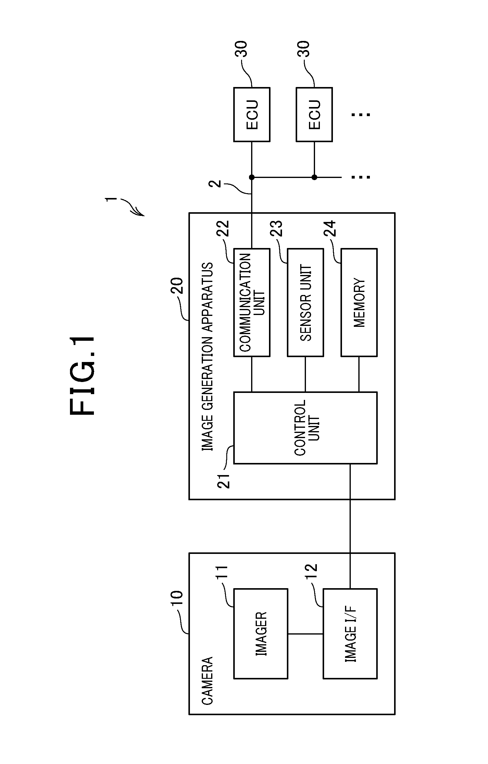
[0023]As shown in FIG. 1, an image generation system 1 according to a first embodiment is mounted in a vehicle (hereinafter referred to as an “own vehicle”), and includes a camera 10 that captures an image of a periphery of the own vehicle, an image generation apparatus 20, and the like.

[0024]The camera 10 includes an imager 11, an image interface (I / F) 12, and the like.

[0025]The imager 11 includes an image sensor, an amplifying unit, an analog-to-digital (A / D) converting unit, and the like. The image sensor may be a charge-coupled device (CCD) image sensor or a complementary metal-oxide-semiconductor (CMOS) image sensor.

[0026]In the imager 11, when the image sensor captures an image, the amplifying unit amplifies an analog signal outputted from the image sensor, by a predetermined gain. The analog signal indicates luminance (brightness) of each pixel in the captured image. In addition, the A / D converting unit converts an analog value indicated by the...

second embodiment

[0064]Next, the image generation system 1 according to a second embodiment will be described. The image generation system 1 according to the second embodiment is configured by the camera 10 and the image generation apparatus 20 similar to those according to the first embodiment. However, the content of the processes differs in part. Hereafter, the differences will mainly be described.

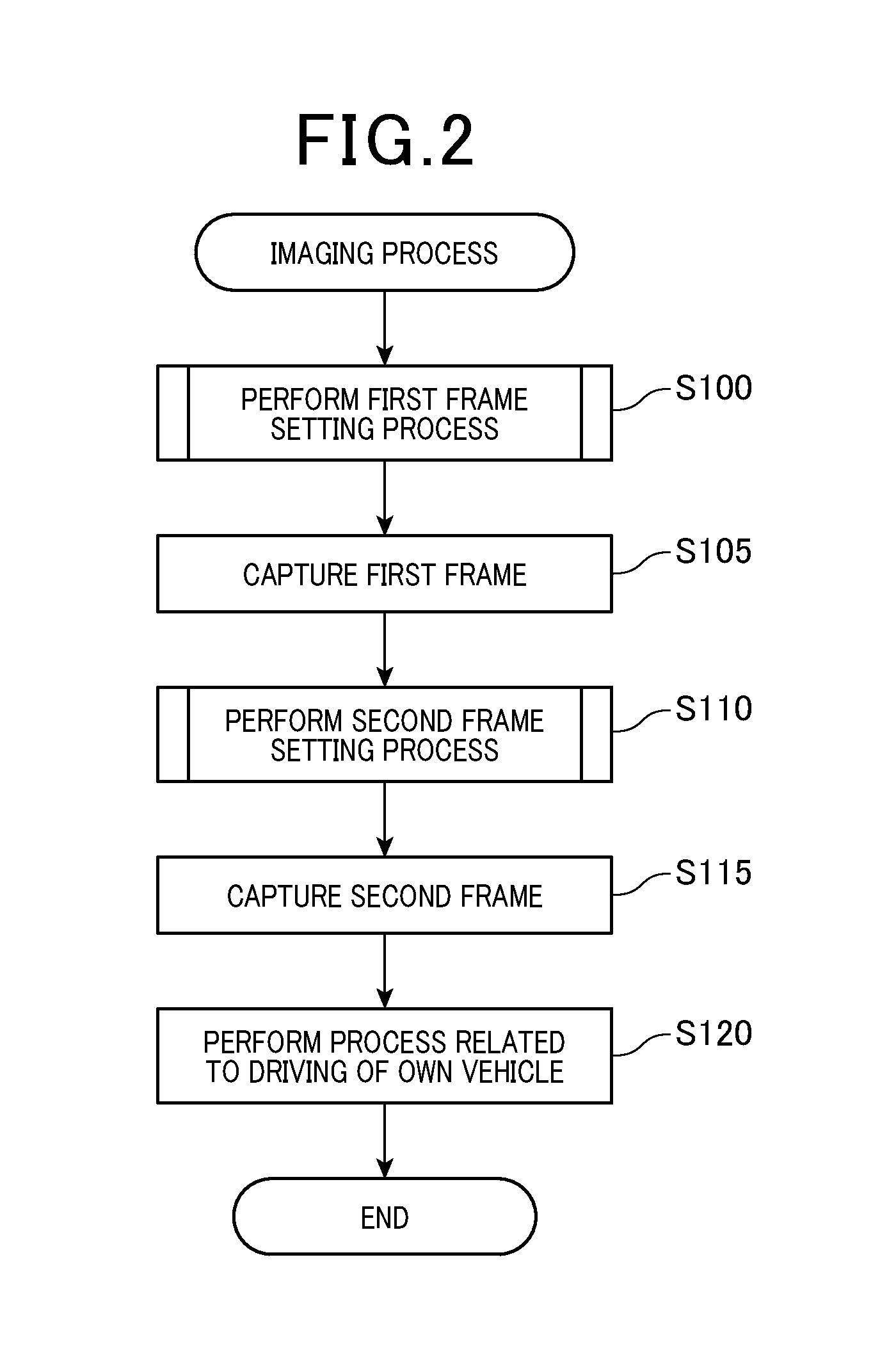
[0065]According to the second embodiment, the image generation apparatus 20 performs the imaging process when a periodic imaging timing arrives. The first and second frames are thereby captured. However, the method for capturing the second frame differs from that according to the first embodiment.

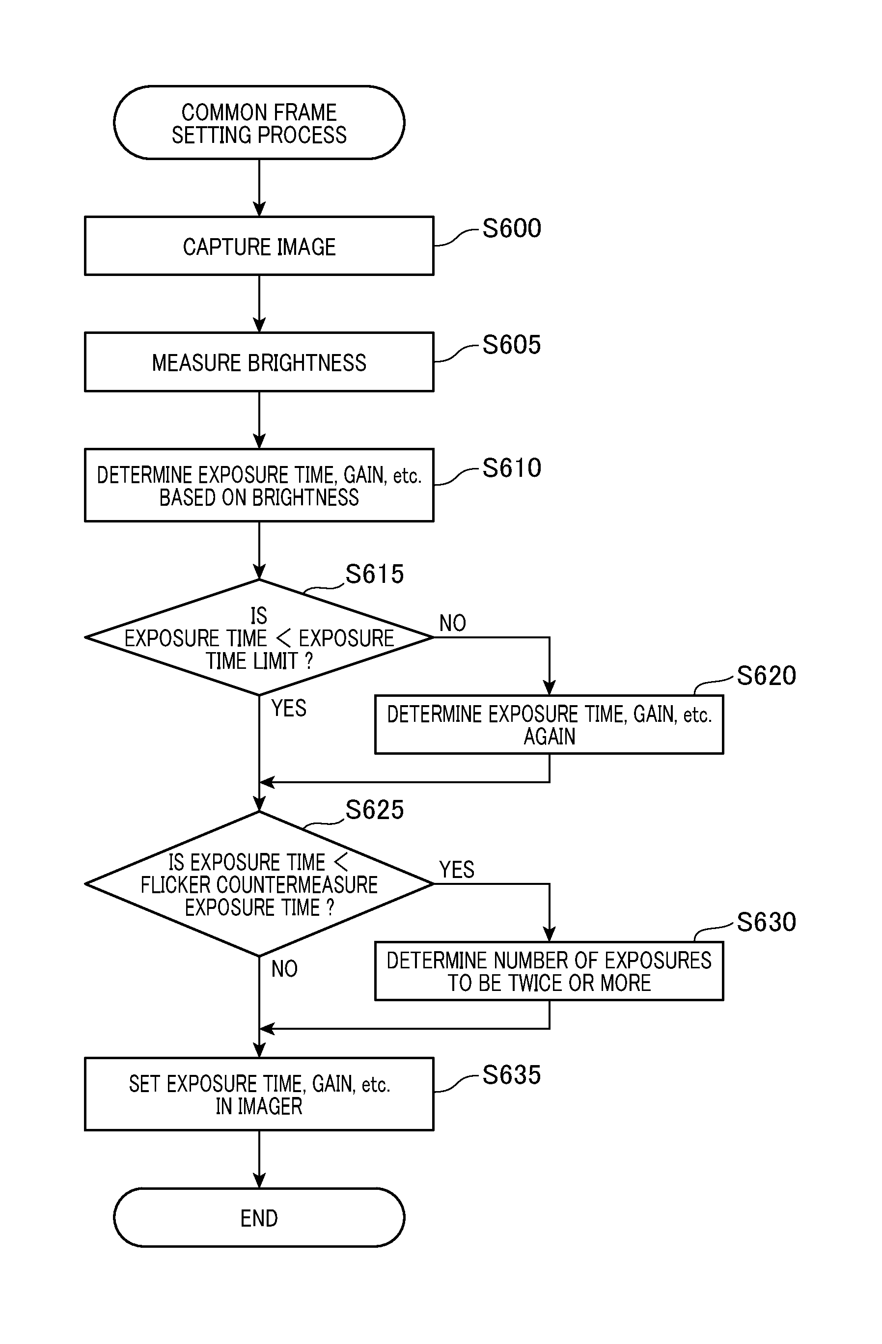
[0066]Specifically, according to the second embodiment, when the imaging timing arrives, imaging is continuously performed twice (FIG. 6). Here, the exposure time is set to that enabling the number of pixels in which saturation occurs to be kept at a level prescribed in advance or less (for example, an amount o...

third embodiment

[0076]Next, the image generation system 1 according to the third embodiment will be described. The image generation system 1 according to the third embodiment is configured by the camera 10 and the image generation apparatus 20, similar to those according to the second embodiment. Processes similar to those according to the second embodiment are performed. However, the method for capturing the second frame differs from that according to the second embodiment.

[0077]Specifically, according to the third embodiment, when the imaging timing arrives, the second frame is continuously captured using three imaging operations (FIG. 6). Here, the exposure time is set to that enabling the number of pixels in which saturation occurs to be kept at a level prescribed in advance or less (for example, an amount of time that is about one-third the period assumed as the flashing cycle of an electronic sign). The second frame is generated as a result of these captured images being combined.

[0078]The nu...


PUM


Abstract

In an image generation apparatus, an image of a periphery of an own vehicle is captured using an imaging operation of a camera mounted in the own vehicle in a first state that is suitable for capturing an image for recognizing information illustrated on a display board, at a predetermined first timing, and a first captured image is generated from the image captured in the first state. An image of the periphery of the own vehicle is captured using an imaging operation of the camera in a second state that is suitable for capturing an image for recognizing information displayed by light emitted from an electronic display apparatus, at a predetermined second timing, and a second captured image is generated from the image captured in the second state. A process using the first captured image and the second captured image is performed.

Description

CROSS-REFERENCE TO RELATED APPLICATION[0001]This application is based on and claims the benefit of priority from Japanese Patent Application No. 2015-103571, filed May 21, 2015. The entire disclosure of the above application is incorporated herein by reference.BACKGROUND[0002]Technical Field[0003]The present disclosure relates to an image generation apparatus.[0004]Related Art[0005]A technique is known in which, when an image of the periphery of an own vehicle is captured, exposure time is set based on a vehicle speed of the own vehicle and brightness of the periphery of the own vehicle. Blurring of the captured image is thereby kept within a certain range (refer to Japanese Patent Publication No. 5421999). As a result, the accuracy of recognition of a sign illustrated on a display board or the like from the captured image is improved.[0006]However, when the exposure time is shortened to reduce blurring, flicker occurs when an image of an electronic display apparatus is captured. Th...

Claims


Application Information

Patent Timeline
Patent Type & Authority Applications(United States)
IPC IPC(8): H04N5/235B60R1/00G05D1/02H04N5/247
CPCH04N5/2352H04N5/247H04N5/2357H04N5/2355G06K9/209B60R1/00G05D1/0246G06K9/00791H04N5/2351G03B7/003H04N23/745H04N23/71H04N23/73H04N23/76
Inventor MURAO, TOSHIKAZU
Owner DENSO CORP
Why Eureka
Try Eureka