Downlink mode of transmission, network devices and wireless device in the coordinated multiple-point transmission systems

A technology of multi-point transmission and transmission method, which is applied in the field of network equipment, wireless system, and downlink transmission method, which can solve problems such as the mismatch of coverage data channels, channel interference, and affecting the effective coverage of cooperative cells, so as to improve the effective coverage range, to avoid mutual interference effects

Inactive Publication Date: 2010-07-14
HUAWEI TECH CO LTD
View PDF2 Cites 83 Cited by
  • Summary
  • Abstract
  • Description
  • Claims
  • Application Information

AI Technical Summary

Problems solved by technology

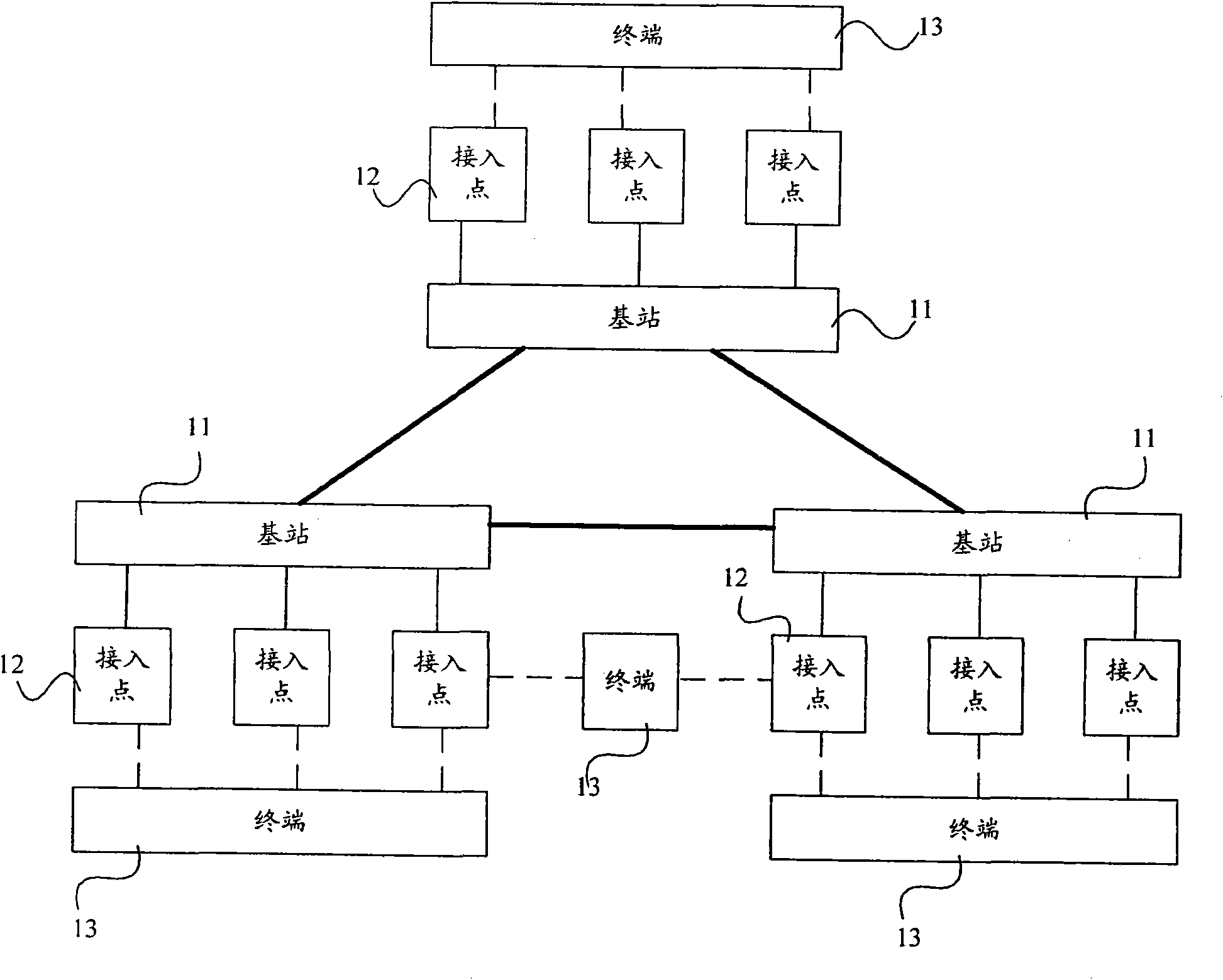
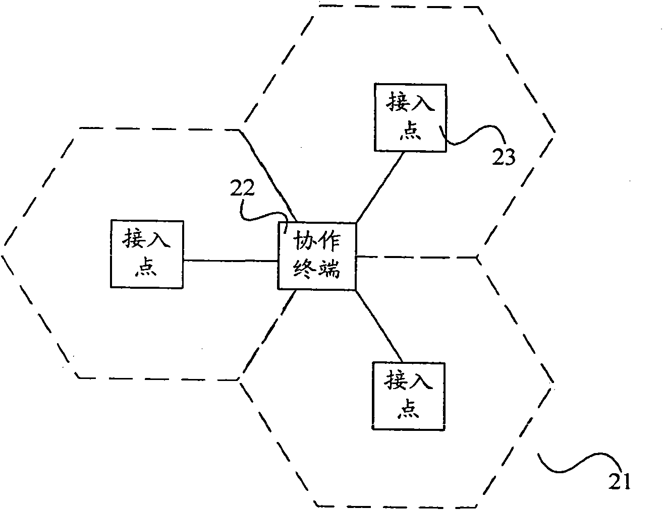
[0003] In the process of implementing the present invention, the inventor found that the prior art has at least the following problems: for the control channel, if it is sent by only one cell, its coverage does not match the data channel, which affects the effective coverage of the cooperative cell. , if each cell sends control information separately, the channels sent to the same user will interfere with each other, resulting in a decline in receiving performance, and the expected effect cannot be optimally achieved

Method used


Image

  • Downlink mode of transmission, network devices and wireless device in the coordinated multiple-point transmission systems
  • Downlink mode of transmission, network devices and wireless device in the coordinated multiple-point transmission systems
  • Downlink mode of transmission, network devices and wireless device in the coordinated multiple-point transmission systems

Examples


example 1

[0100]Cell1 and Cell2 allocate the same PRB as a dedicated PRB for CoMP, and only the channels for sending information to UE1-1 and UE2-1, which are terminals in the CoMP state, can use the dedicated PRB. Cell1 and Cell2 can form a virtual cell with these two parts of dedicated PRBs, and assign a special CoMP cell identifier, ie CoMP-ID, to identify it (set CoMP-ID=100).

[0101] CoMP-ID is configured for Cell1 and Cell2, and UE1-1 and UE2-1 belong to the CoMP virtual cell with CoMP-ID=100. UE1-1 and UE2-1 are notified of CoMP-ID, further, UE1-1 is also notified of Cell-ID1, and UE2-1 is also notified of Cell-ID2.

[0102] The coordinated cell further obtains the PRB corresponding to the CoMP-ID and the corresponding downlink PRB mapping rule obtained by the CoMP-ID, and uses the PRB to send CoMP downlink control information. At the same time, UE1-1 can receive other cell configuration information of Cell1, and UE2-1 can also receive other cell configuration information of Ce...

example 2

[0104] Cell1 allocates PRBs to UE1-1 and UE1-2; Cell2 allocates PRBs to UE2-1. When Cell1 and Cell2 are allocated, coordinate so that the PRBs of UE1-1 and UE2-1 can cooperate to perform CoMP; at the same time, the PRBs allocated by Cell1 to UE1-2 will not be different from the PRBs of UE1-1 and UE2-1 in the CoMP state impact of conflict. For example: the allocated physical downlink control channels of UE1-1 and UE2-1 respectively correspond to different PRBs, so as to avoid mutual interference. UE1-2 is also allocated to a different PRB from UE2-1, but UE1-1 and UE2-1 can be allocated to the same PRB.

[0105] The downlink information in this embodiment is sent by the physical downlink channel negotiated by multiple coordinated cells. The coordinated cells that perform coordinated allocation and control of downlink physical resources may be all coordinated cells in the virtual cell that performs CoMP, or may perform CoMP. Some cooperative cells in the virtual cell.

[0106...


PUM


Abstract

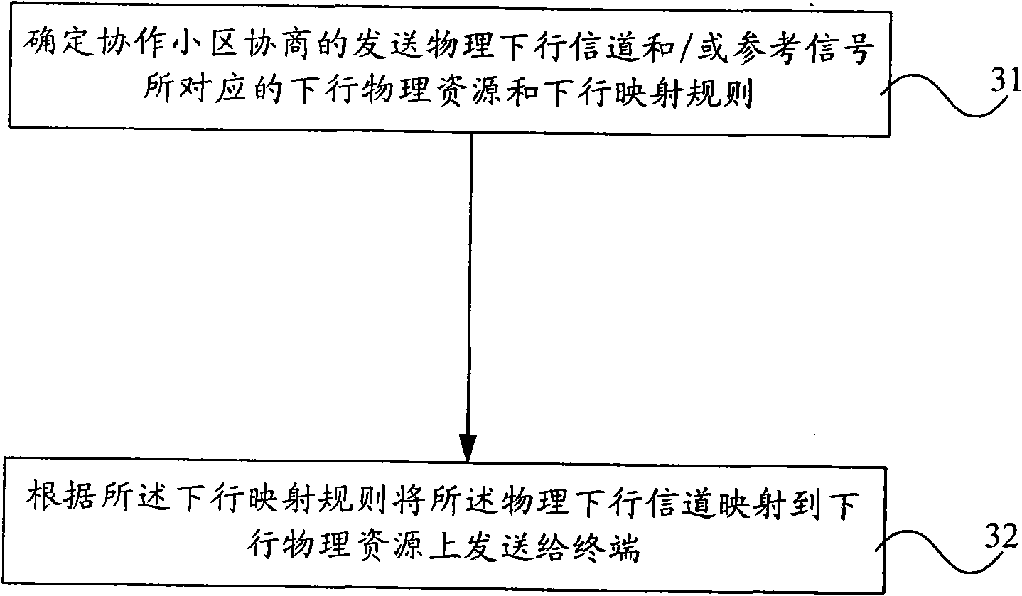
The invention discloses a downlink mode of transmission, network devices and a wireless device in the coordinated multiple-point transmission systems. The method includes the following steps: make clear the correspondent downlink physical resources and downlink mapping rules to the established sending physical downlink data channel and / or reference signal of the cooperation community. The downlink channel and / or reference signal are mapped to the downlink physical resources according to the downlink principles and then delivered to the terminals. The embodiment of the invention can expand the effective coverage, and to avoid interference between different communities.

Description

technical field [0001] The present invention relates to wireless communication technology, in particular to a downlink transmission method, network equipment and wireless system in a coordinated multi-point transmission system. Background technique [0002] In a wireless communication system, in order to improve the downlink transmission performance of cell edge users, downlink coordinated multi-point transmission in the Coordinated Multi-Point transmission (CoMP for short) technology can be used, that is, multiple cells jointly transmit data to the same terminal. The transmission data channel is used to enhance the signal to interference-and-noise ratio (SINR) of the signal received by the terminal or to improve the throughput of system transmission. Among them, multiple cells that use CoMP technology to transmit data channels to the same terminal are called cooperative cells, and cooperative cells can be divided into anchor cells (Anchor Cell) and serving cells (Serving Ce...

Claims


Application Information

Patent Timeline
Patent Type & Authority Applications(China)
IPC IPC(8): H04B7/02H04W28/18
CPCH04W72/042H04J11/0053H04B7/024H04W72/23
Inventor 万蕾赵亚军程型清任晓涛
Owner HUAWEI TECH CO LTD
Why Eureka
Try Eureka