

Advanced strap pipe wrench for driving an object having a generally cylindrical shape
A pipe wrench, object technology, applied in application, wrench, liquid handling, etc., can solve the problem of time-consuming strap adjustment stage
- Summary
- Abstract
- Description
- Claims
- Application Information
AI Technical Summary
Problems solved by technology
Method used
Image

Examples
Embodiment Construction
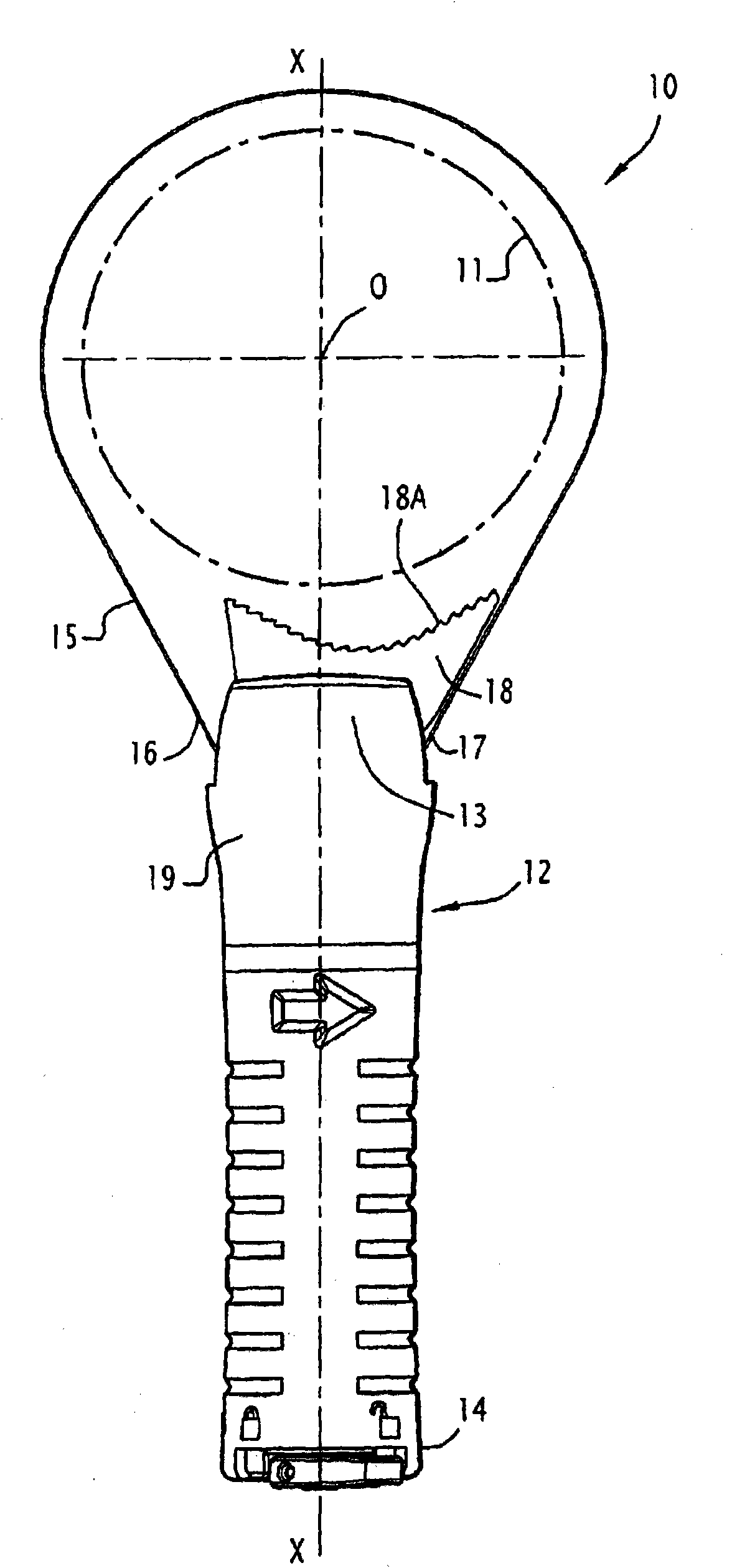
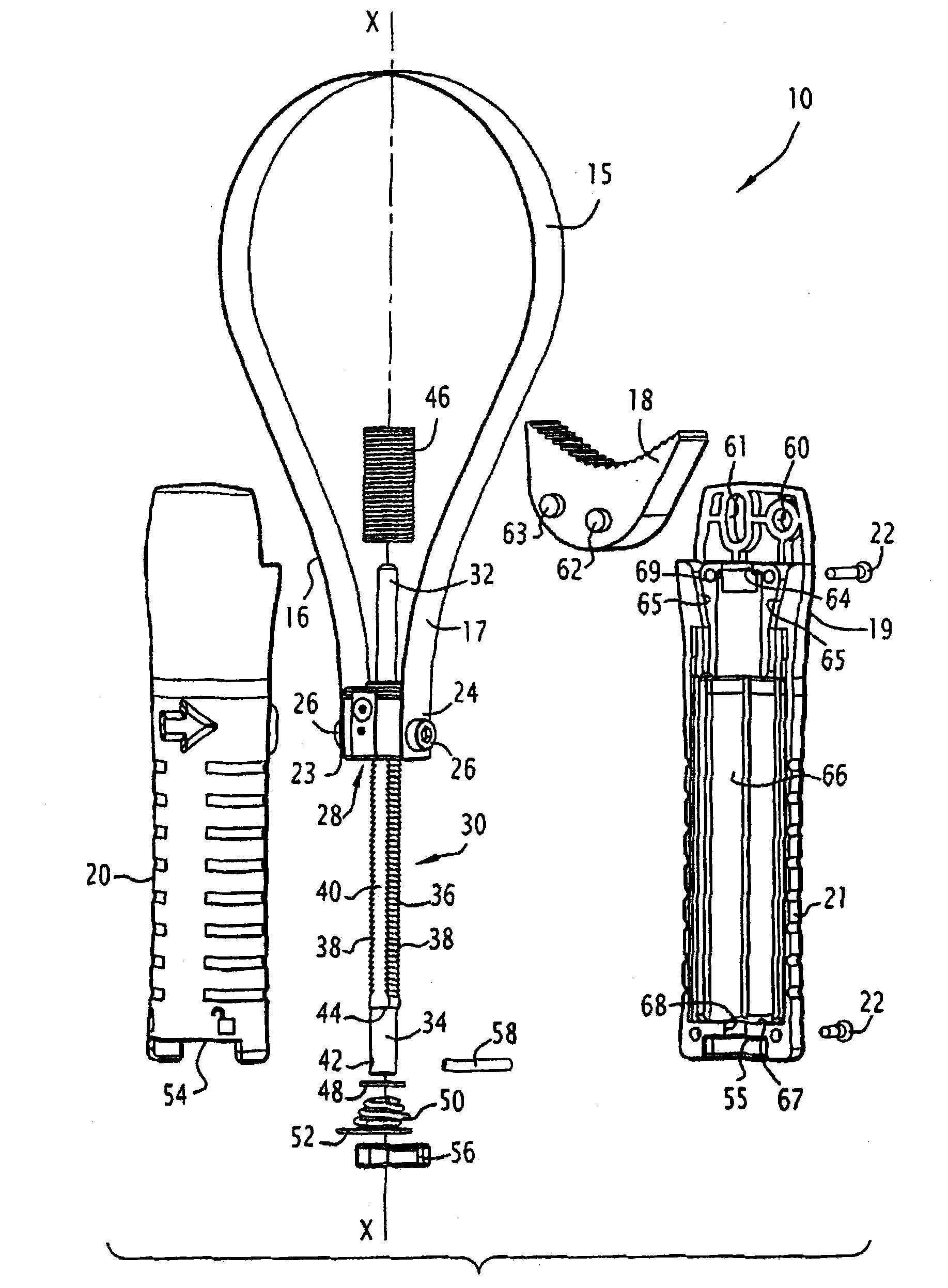
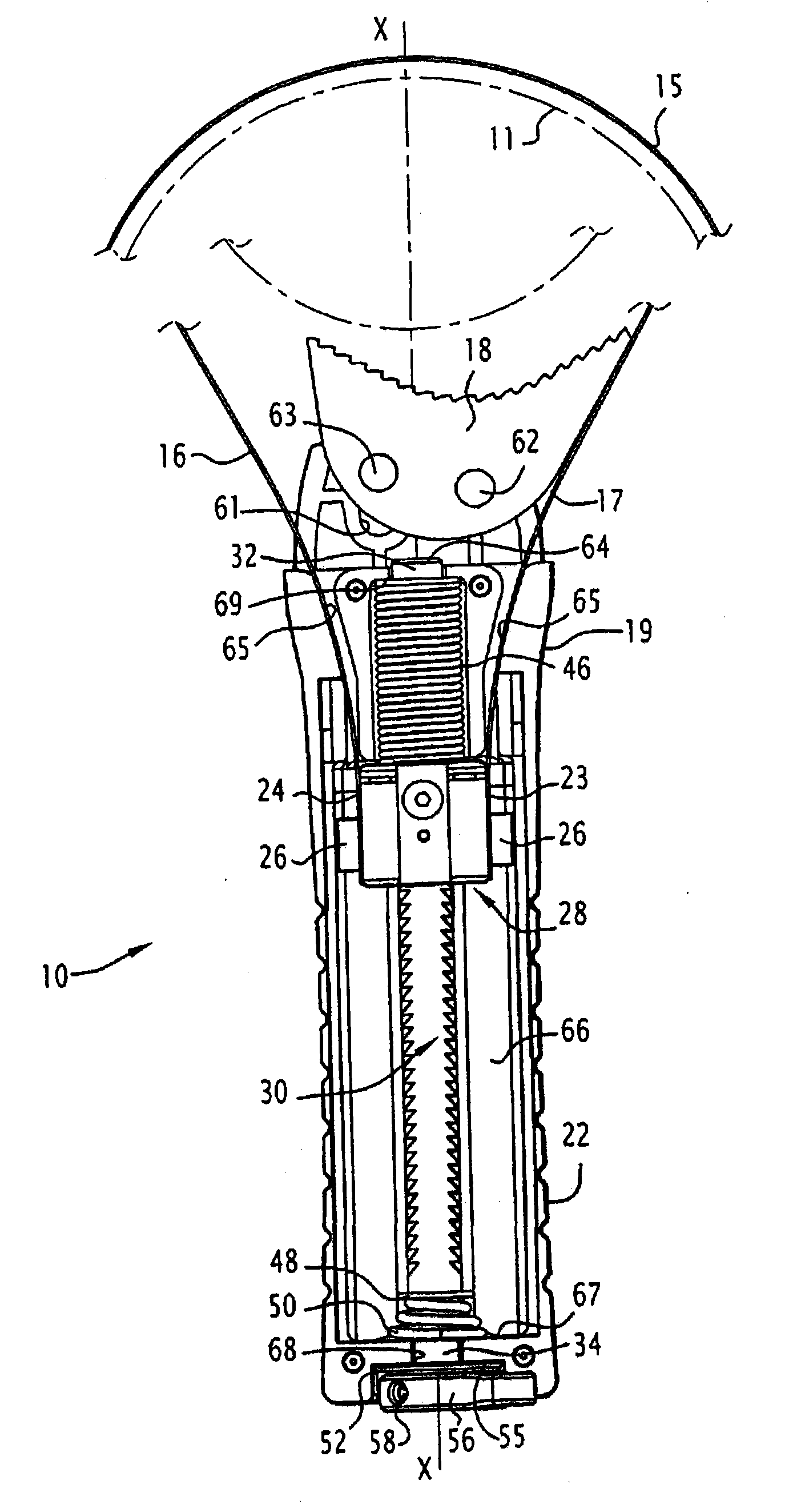
[0042] exist Figure 1 to Figure 12 The band-type pipe wrench 10 shown in is mainly used for dismantling and concomitantly tightening generally cylindrical objects 11, in particular oil filters, the diameter of which can be within a wide range by turning the pipe wrench Variations, such as a diameter of 64 mm to 106 mm in the embodiment shown.
[0043] To describe the pipe wrench 10 more conveniently, it is assumed that the pipe wrench is placed in the orientation shown in the figure, which extends along the longitudinal axis X-X, and the axis O of the filter 11 is located above the handle of the pipe wrench.
[0044] exist figure 1 Here, a band pipe wrench 10 comprises a handle 12 having a distal portion 13 and a proximal portion 14, the distal portion 13 forming a forked joint with wings parallel to the plane of the drawing.
[0045] The strap 15 is in particular a metal strap and forms an endless strap, the strap 15 comprising two end pieces 16 and 17 connected to the han...
PUM
 Abstract
Description
Claims
Application Information