Floor pipe wrench

A pipe wrench and workbench technology, applied in the field of clamping tools, can solve the problems of low work efficiency, physical exertion, inconvenience in carrying, moving and operation, etc.

Inactive Publication Date: 2013-06-26
李乃生
View PDF6 Cites 5 Cited by
  • Summary
  • Abstract
  • Description
  • Claims
  • Application Information

AI Technical Summary

Problems solved by technology

[0002] In industrial production, a variety of commonly used tools are involved in the operation of pipe fittings, such as pipe wrench, pressure pliers, etc. These tools are simple in structure, but relatively heavy. Pressure pliers are common tools for clamping and fastening. It is simple, but it is inconven

Method used


Image

  • Floor pipe wrench
  • Floor pipe wrench

Examples


Embodiment Construction

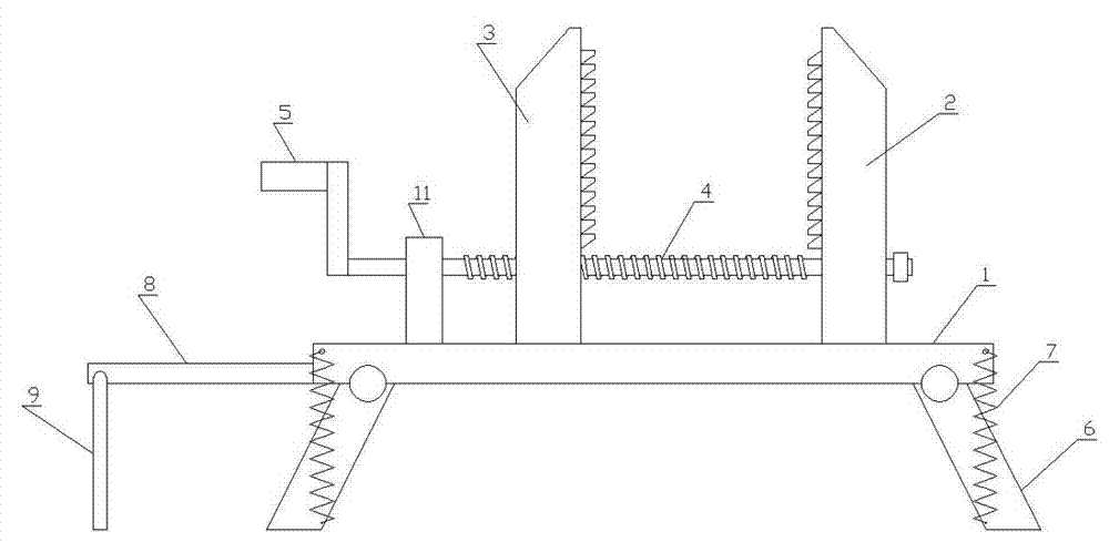
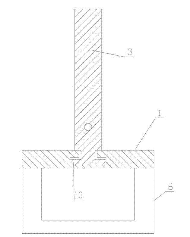
[0010] Such as figure 1 and figure 2 As shown, a floor pipe wrench of the present invention includes a workbench 1, a propulsion shaft 4, a fixed column 2, a moving column 3, a reaction force frame 11, a stabilizing column 8 and a rocking bar 5, and the reaction force frame 11, the fixed column 2 respectively fixed on both sides of the workbench 1, the workbench 1 is provided with a track groove, the lower part of the moving column 3 is provided with a track clip 10, and the track clip 10 is placed in the track groove on the workbench 1, the The propulsion shaft 4 passes through the reaction force frame 11, the fixed column 2 and the moving column 3 successively. The said propulsion shaft 4 is provided with threads and is threadedly matched with the moving column 3. The workbench 1 is hinged with a bracket 6, and the stable One end of the column 8 is screwed into the transverse screw hole on the side of the workbench 1 , and the other end of the stabilizing column 8 is hinge...


PUM


Abstract

The invention discloses a floor pipe wrench. The floor pipe wrench comprises a workbench, a propeller shaft, a fixed post, a movable post, a counter-force frame, a stable post and a rocking bar, wherein the counter-force frame is fixedly connected with the two sides of the workbench, respectively; a rail slot is arranged on the workbench; a rail fastener is arranged on the lower part of the movable post; the rail fastener is arranged in the rail slot on the workbench; the propeller shaft penetrates through the counter-force frame, the fixed post and the movable post in sequence; threads are formed on the propeller shaft and matched with the threads of the movable post; and a bracket is hinged below the workbench. Compared with the existing pressure clamp, the size is remarkably reduced, the portable performance is good, the environmental adaptation is stronger and the manufacturing cost is remarkably lowered.

Description

technical field [0001] The invention relates to a clamping tool, in particular to a floor pipe wrench. Background technique [0002] In industrial production, a variety of commonly used tools are involved in the operation of pipe fittings, such as pipe wrench, pressure pliers, etc. These tools are simple in structure, but relatively heavy. Pressure pliers are common tools for clamping and fastening. It is simple, but it is inconvenient to carry, move and operate. In some cases, more than two operators are required to cooperate to complete the use, which consumes physical strength and low work efficiency. In some special working environments, due to its structure, weight and other reasons, it may not be able to complete the expected operation tasks. Contents of the invention [0003] The purpose of the present invention is to overcome the deficiencies of the prior art and provide a floor-standing pipe wrench, which is easy to carry and can better clamp and fasten component...

Claims


Application Information

Patent Timeline
IPC IPC(8): B25B13/50
Inventor 李乃生
Owner 李乃生
Why Eureka
Try Eureka