Pipe wrench

A pipe wrench and movable clamp technology, applied in the direction of wrenches, wrenches, screwdrivers, etc., can solve the problems of reducing the friction force of the bite point, affecting the effect of the pipe wrench on the clamped object, and slipping.

Inactive Publication Date: 2009-06-10
MH
View PDF5 Cites 5 Cited by
  • Summary
  • Abstract
  • Description
  • Claims
  • Application Information

AI Technical Summary

Problems solved by technology

[0003] The aforementioned pipe wrench further utilizes the pivoting of the movable jaws to match the different diameters of the clamped objects to open and close, but when the swing of the movable jaws exceeds a certain angle, it will immediately make the movable jaws and the fixed jaws The occlusal teeth cannot effectively occlude the surrounding surface of the clamped object, resulting in reduced friction at the occlusal point, resulting in slippage, which affects the effect of the pipe wrench on the clamped object, causing user inconvenience and trouble in operation

Method used


Image

  • Pipe wrench
  • Pipe wrench
  • Pipe wrench

Examples


Embodiment Construction

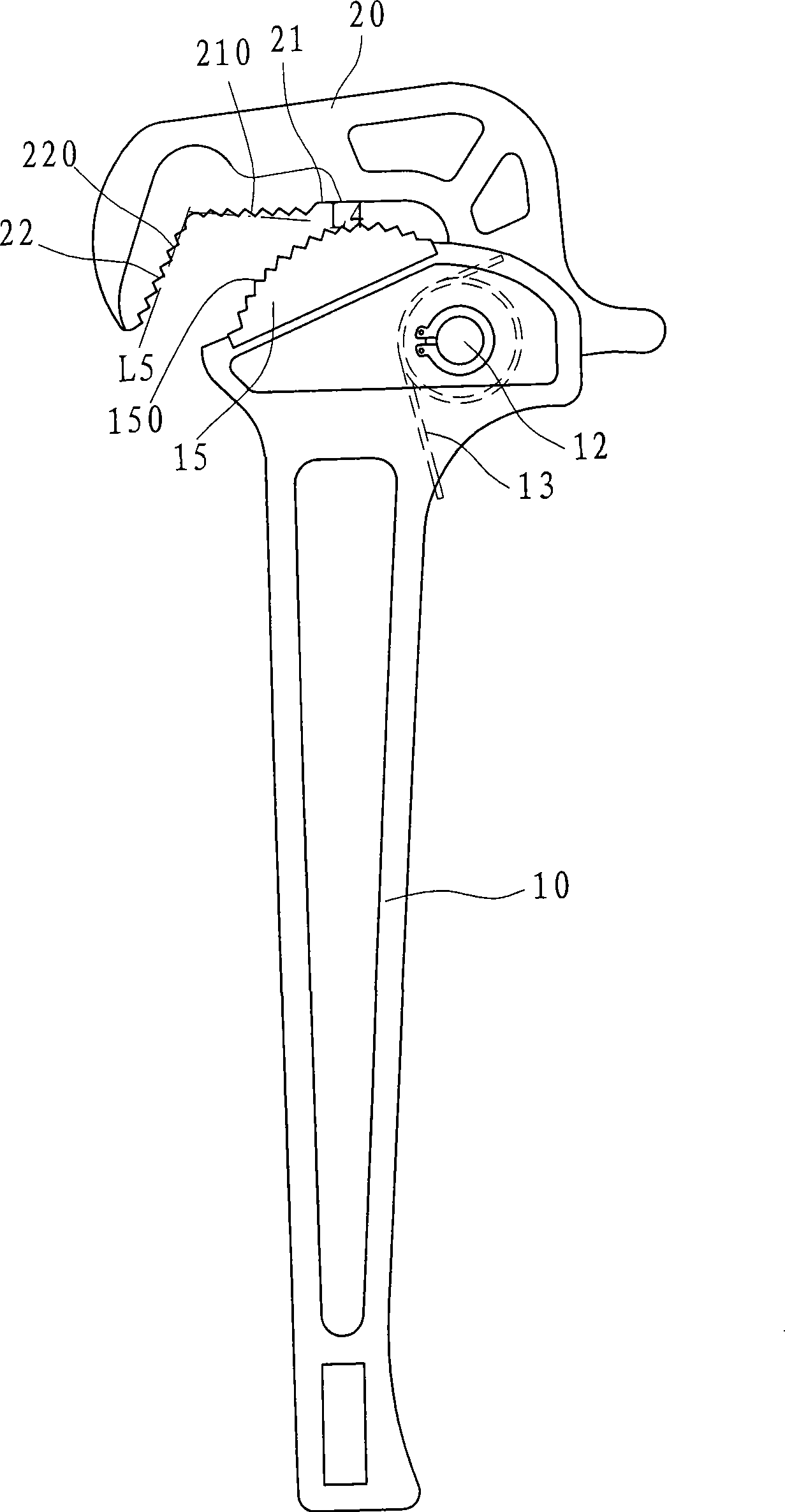
[0024] The invention relates to a pipe wrench for clamping objects such as round pipes or rods, such as figure 1 As shown, the pipe wrench structure of the present invention has a long rod-shaped handle 10, at least one of the two ends of the handle 10 is pivoted with a movable jaw 20 by a pivot 12, and the handle 10 corresponds to the end lock of the opening of the movable jaw 20. An arc-shaped jaw block 15 is provided;

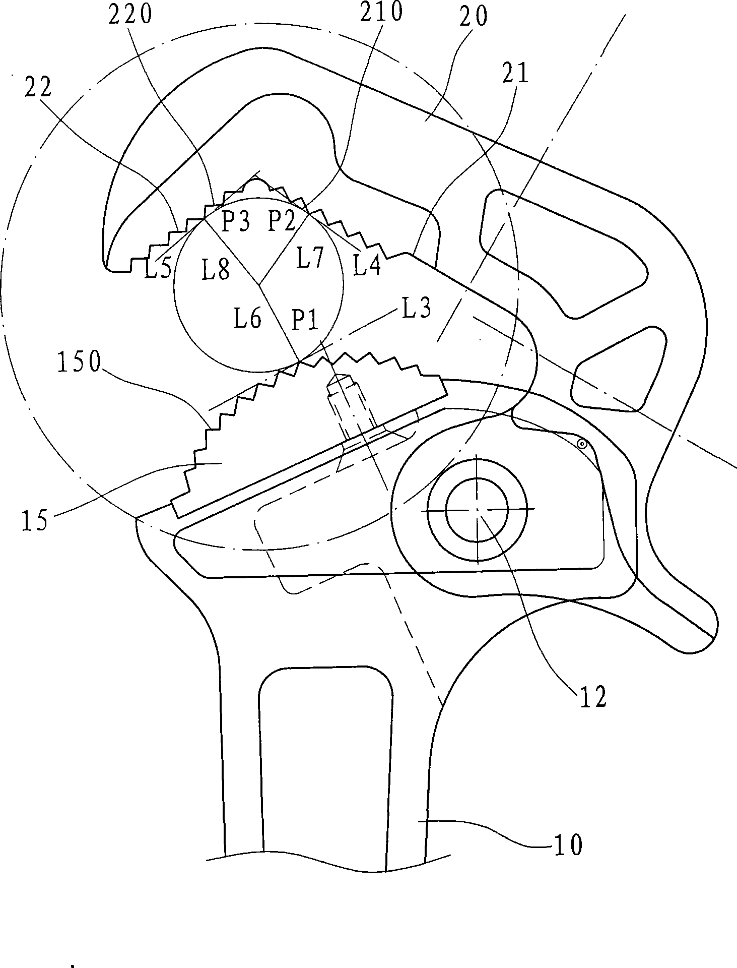
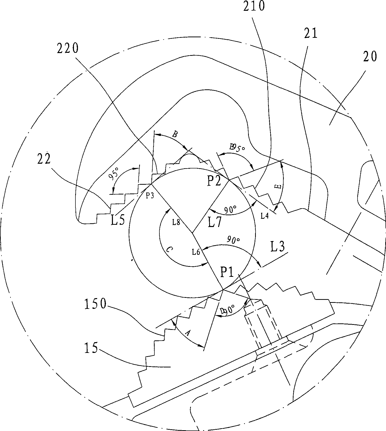
[0025] And about the detailed description of the characteristic step of the present invention, then please refer to simultaneously figure 1 , figure 2 , image 3 As shown, the structure of the pipe wrench is provided with a torsion spring 13 on the pivot 12 between the movable jaw 20 and the handle 10, and the protruding feet at both ends of the torsion spring 13 are supported on the opposite inner surfaces of the handle 10 and the movable jaw 20 respectively. , so that the movable jaw 20 can be automatically occluded relative to the arc-shaped jaw block...


PUM


Abstract

The invention relates to a structure of pipe tongs. The pipe tongs comprise a handle and a movable clamping jaw, wherein the top surface of the handle is fixedly provided with an arc-shaped jaw block. The movable clamping jaw is pivoted at the top end of the handle and is made clamp and close relative to the arc-shaped jaw block of the handle through a torsion spring. The inner surface of the movable clamping jaw has a first tooth surface and a second tooth surface which are in opposite horizontal V shapes. The included angle between the first tooth surface and the second tooth surface is 135 degree. The included angles between an occlusion point of the first tooth surface of the movable clamping jaw and an occlusion point of the arc-shaped jaw block and the perpendicular dividing line of the center of a clamped object are between 160 and 170 degrees. The pipe tongs of the invention can prevent an circular object clamped from moving toward the opening between the movable clamping jaw and the arc-shaped jaw block, apply a major part of force on a circular surface perpendicular to the occlusion points, and generate larger friction forces on the occlusion points to prevent a pipe from deforming or sliding when the jaw block and the clamped object occlude.

Description

technical field [0001] The invention belongs to the technical field of clamping of circular pipes or rods, and specifically refers to a pipe wrench structure with high friction, so as to increase the bite and clamping force of the pipe wrench relative to the clamped object. Background technique [0002] In order to effectively clamp round pipes or rods, the industry has developed a variety of pipe clamps, such as US patent US 2,559,973 and US 6,026,714 and other patents. The fixed jaw block of the teeth, and the top of the handle is pivotally equipped with a movable jaw that can be clamped or separated from the fixed jaw block. The inner surface of the movable jaw is also formed with a plurality of occlusal teeth opposite to the occlusal teeth of the fixed jaw. In the aforementioned patent, the multiple occlusal teeth of the fixed jaw extend in an arc shape, while the occlusal teeth on the inner surface of the movable jaw form two The extended surface of the included angle ...

Claims


Application Information

Patent Timeline
Patent Type & Authority Applications(China)
IPC IPC(8): B25B13/50B25B23/00
Inventor 游秋莹
Owner MH
Why Eureka
Try Eureka