Pipe fitting socket for use with an axial drive mechanism

a technology of axial drive mechanism and pipe fitting, which is applied in the direction of wrenches, bends, screwdrivers, etc., can solve the problems of pipe installation that is extremely inconvenient, the socket is prone to axial drive, and the space is at a premium during installation, so as to facilitate the torquing of the socket

Inactive Publication Date: 2010-09-07
NICOLAZZO RANDY +1
View PDF9 Cites 5 Cited by
  • Summary
  • Abstract
  • Description
  • Claims
  • Application Information

AI Technical Summary

Problems solved by technology

Several problems exist with the current state of the art in pipe fitting installation and removal, especially when said installation and / or removal occurs in limited access areas.
Where angled fittings have been installed in confined spaces or where surrounding equipment has been installed after an initial pipe installation, conventional pipe wrenches can render pipe installation extremely inconvenient.
This is because conventional pipe wrenches require the use of a long handle, which places space at a premium during installation.
This problem is further exacerbated by the bulkiness of the jaw of a conventional pipe wrench, which often severely restricts the jaw's range of movement.
Compounding the problem is the fact that the first part of the tightening movement is lost to the rocking jaw movement until it tightens enough to be able to turn the fitting.
Consequently, pipe installation and removal professionals are either forced to remove and reinstall surrounding equipment or else struggle to work around it, using a wrench limited to a very small effective range of movement (10 to 20 degree effective range is not uncommon).
Under these conditions, pipe and fitting assembly is frustratingly slow, excessively difficult and inefficient.
The tendency for conventional pipe wrenches to slip while being forcefully turned adds to the difficulty of tight quarters work and also adds risk of injury to piping professionals and / or damage to nearby equipment and structures.
Additionally, the slippage inherent in conventional pipe wrenches can decrease overall productivity.
Finally, the teeth in conventional pipe wrenches tend to mar and / or score pipe / fitting surfaces.

Method used


Image

  • Pipe fitting socket for use with an axial drive mechanism
  • Pipe fitting socket for use with an axial drive mechanism
  • Pipe fitting socket for use with an axial drive mechanism

Examples


Embodiment Construction

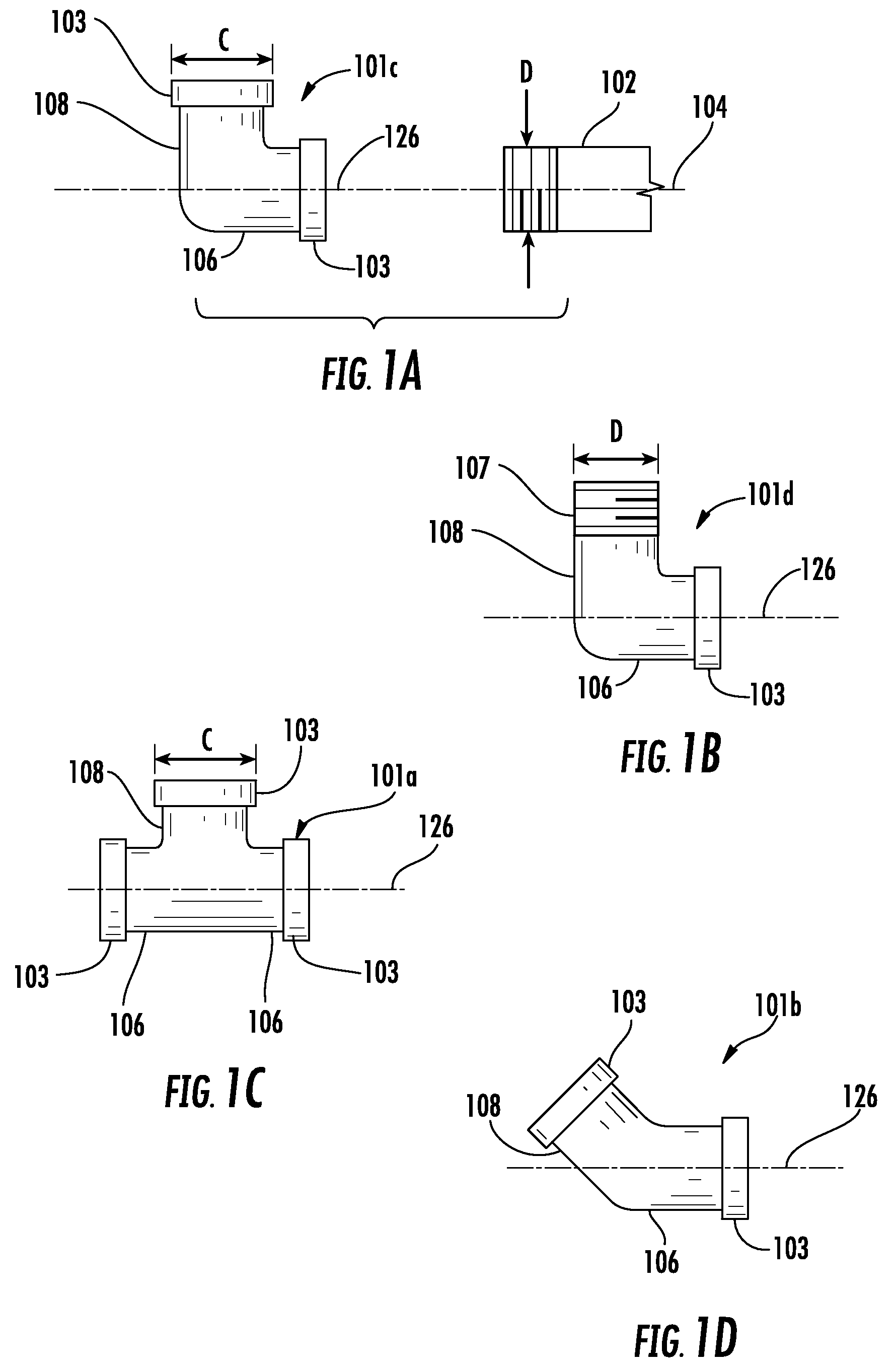
[0027]Although the drawings and the proceeding description disclose angled fittings with female threaded ends (the most common form), it should be understood that the inventive socket accepts angled fittings with male or female threaded ends. The use of angled fittings with female threaded ends in the drawings and proceeding description is meant to be illustrative and is not intended to be limiting in nature.

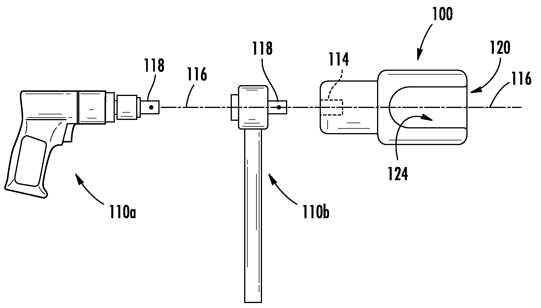
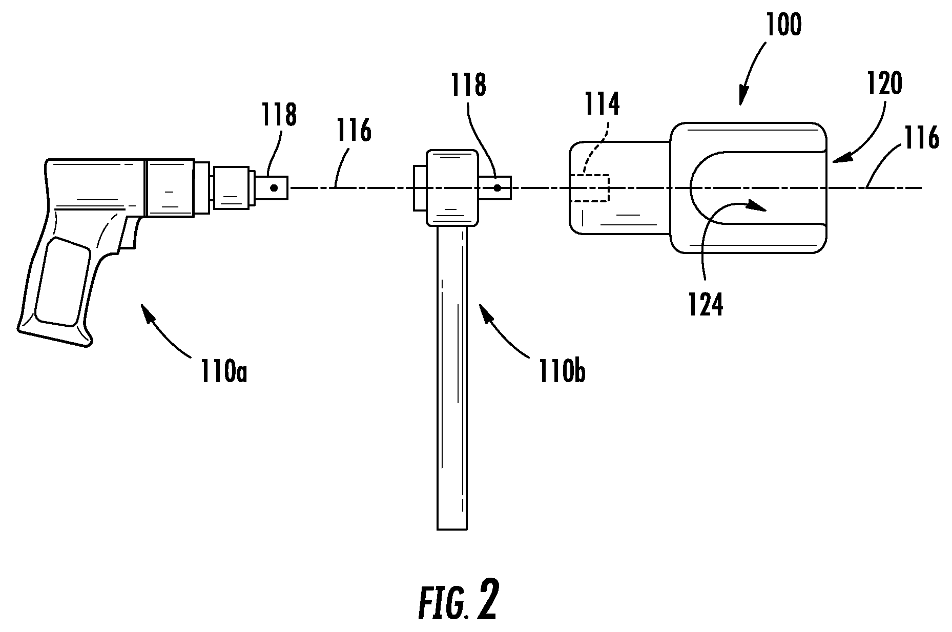
[0028]It will be shown that the inventive socket 100 is particularly suited to advantageously handle a variety of angled pipe fittings, including the most commonly used ones.

[0029]FIG. 1A shows a first example of an angled fitting 101, specifically a full elbow 101c (i.e., a ninety degree elbow), shown coaxially aligned with a fixed threaded end 102 (e.g. a male threaded end of a length of pipe) that has a longitudinal axis 104. The full elbow 101c comprises a lateral arm 108 joined perpendicularly to an axial arm 106, through which runs the axial arm's axis of rotation 126. A f...


PUM


Abstract

A pipe fitting socket for use with an axial driving device accepts a variety of angled fittings (e.g. tees, full elbows, slant elbows) snugly within a fitting cavity for torquing onto a fixed threaded end of pipe. Torquing of the fitting is accomplished by inserting a drive stud of the driving device into a drive aperture defining a rotational axis and torquing the driving device, thereby rotating the socket about the rotational axis, or through manually torquing a cylindrical portion of the socket. The socket offers superior efficiency and safety over conventional pipe wrenches by maximizing the effective range of movement available for a wrench used for angled fitting installation and / or removal, while virtually eliminating a wrench's loss of grip on the fitting.

Description

TECHNICAL FIELD OF THE INVENTION[0001]The present invention relates to plumbing tools, more particularly wrenches for manipulating threaded pipe fittings.BACKGROUND OF THE INVENTION[0002]Pipe fittings are used to join together lengths of pipe. They have two or more fitting ends, connected via short lengths of tubing. Fittings for threaded pipe have at least one fitting end that is threaded, and may be male or female in a variety of different diameters, as needed to threadingly mate with a given threaded pipe end.[0003]Angled fittings have a bend in the tubing between two of the fitting ends. Three of the most common varieties of angled fittings are the elbow fitting, which comprises two female threaded ends joined by a specific angle of tubing (usually 90 degrees, but other angles are available, e.g. 45 degrees, 22.5 degrees); the tee fitting, which comprises three threaded ends, which can be male or female, two of which are joined by a straight length of tubing, and one of which is...

Claims


Application Information

Patent Timeline
Patent Type & Authority Patents(United States)
IPC IPC(8): B25B13/06
CPCB25B13/48B25B13/5091F16L41/021F16L43/00
Inventor NICOLAZZO, RANDYHOLLOMAN, MICHAEL B.
Owner NICOLAZZO RANDY
Why Eureka
Try Eureka