

Dynamic maintenance method and device for related link circuits
A technology for maintaining devices and links, which is applied in data exchange through path configuration, digital transmission systems, electrical components, etc., and can solve the problem that business flows cannot be switched to protect backup links, etc.
- Summary
- Abstract
- Description
- Claims
- Application Information
AI Technical Summary
Problems solved by technology
Method used
Image

Examples
Embodiment 1
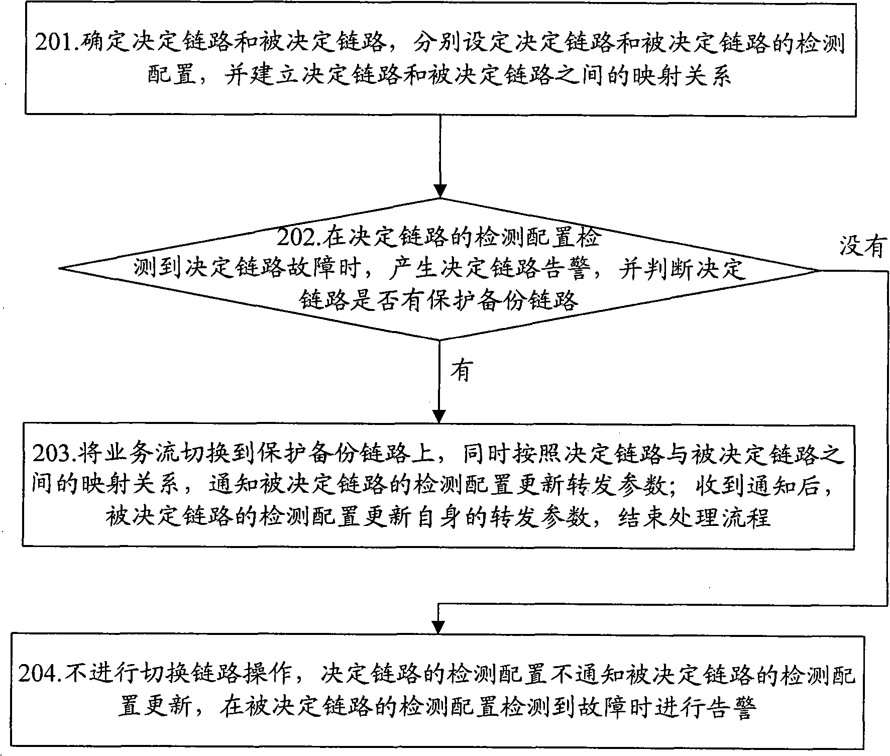
[0064] Embodiment one: in such as figure 1 In the shown topology, the method for implementing dynamic maintenance of associated links in this embodiment is as follows: Figure 4 As shown, the method includes the following steps:
[0065] Step 401: Establish a mapping relationship between the determined link and the determined link detection configuration;
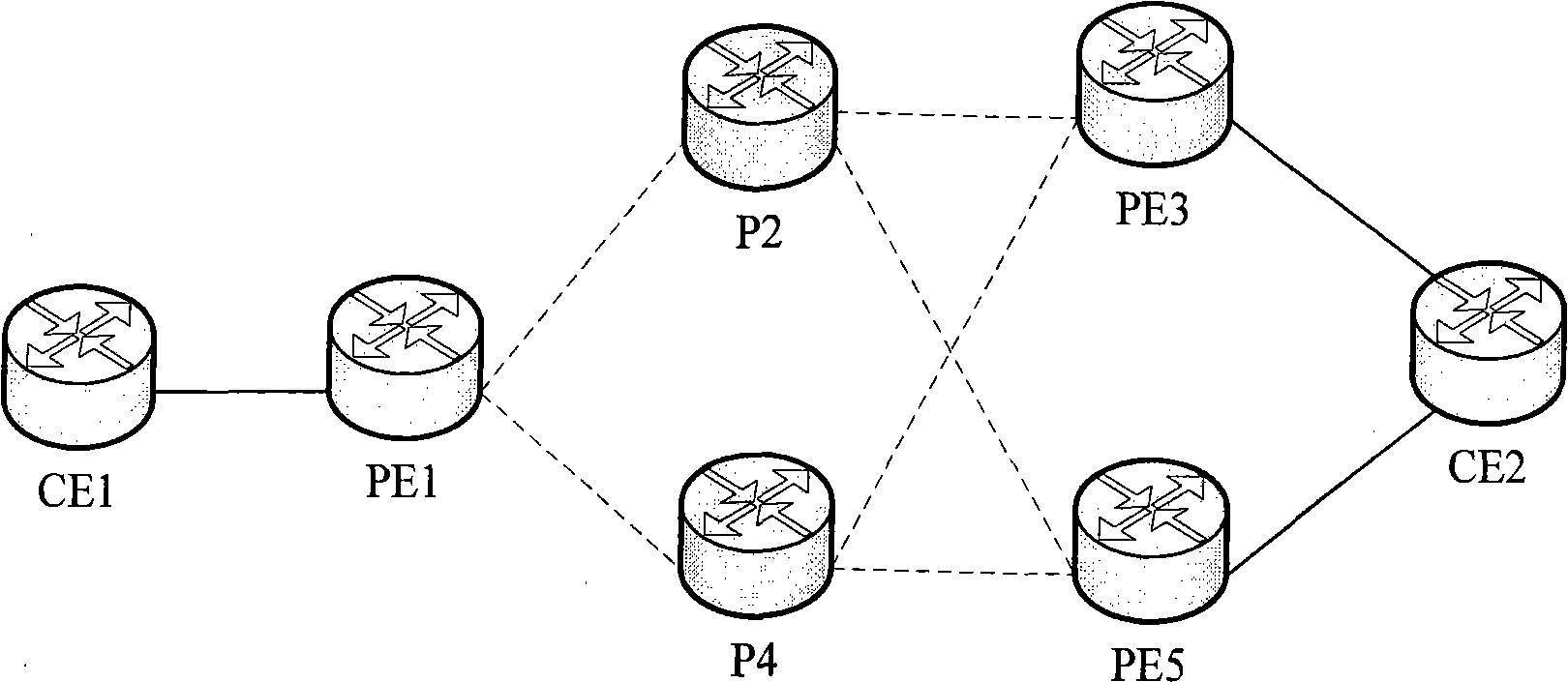
[0066] Specifically, the CE1 node connects to the CE2 node through dual-regulation of the PE1 node, first establishes the tunnel PE1-P2-PE3 as the main tunnel link, that is, determines the link, and configures the protection backup tunnel PE1-P4-PE3, also known as the link As a protection backup link; then configure the pseudowire link PW1 associated with it on the determined link PE1-P2-PE3, that is, the determined link.
[0067] On PE1 and PE3 nodes, set and determine the detection configuration on the link PE1-P2-PE3 to be the detection configuration of the BFD method, which is BFD session 1, which is used to detect th...
Embodiment 2
[0076] Embodiment two: in such as Figure 5 In the shown topology, the dynamic maintenance method of the associated link in this embodiment is as follows: Figure 6 As shown, the method includes the following steps:
[0077] Step 601: Establish a mapping relationship between the determined link and the determined link detection configuration;
[0078] Specifically, the CE1 node connects to the CE2 node through dual-regulation of the PE1 node, first establishes the tunnel PE1-P2-PE3 as the main tunnel link, that is, determines the link, and configures the protection backup tunnel PE1-P4-PE3, also known as the link As a protection backup link; then configure the pseudowire link PW1 associated with it on the determined link PE1-P2-PE3, that is, the determined link.
[0079]Set the detection configuration on the determined link PE1-P2-PE3 to the detection configuration of the TMPLS-OAM method, which is TMPLS-OAM session 1, which is used to detect the failure of the main tunnel; ...
PUM
 Abstract
Description
Claims
Application Information