Intelligent transformer substation voltage switching and paralleling method and device
A technology of voltage switching and voltage, which is applied in the direction of circuit devices, electrical components, information technology support systems, etc., can solve the problems of high device cost, complex data processing, and limitation of working transformer output data communication protocols, etc., to achieve simple and reliable implementation sex high effect
- Summary
- Abstract
- Description
- Claims
- Application Information
AI Technical Summary
Problems solved by technology
Method used
Image


Examples
Embodiment 1
[0034] The steps of the voltage switching method of the double busbar power supply of the present invention are as follows:
[0035] Collect the voltage output of two sets of electronic voltage transformers on the double bus;
[0036] Use the position signals of the two isolated knife switches on the double bus as binary inputs, and collect the status signals of the two binary inputs;
[0037] Control and output the voltage of the corresponding busbar according to the collected voltage output of the two sets of electronic voltage transformers and the corresponding status signal of the input of the isolation switch;
[0038] As shown in the following table 1, when the I bus isolation switch is collected and the II bus isolation switch is withdrawn, the I bus voltage is output; when the II bus isolation switch is collected and the I bus isolation switch is withdrawn, the output II is Bus voltage; when it is collected that both I bus and II bus isolation switches...
Embodiment 2
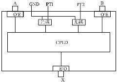
[0041] The voltage switching device for power supply of dual busbars of the present invention is as figure 1 As shown, the device includes:
[0042] The logic controller CPLD (programmable device FPGA can also be used) is used to control the output of the switched voltage according to the collected position signals of the I mother and II mother isolation switch and the corresponding voltage output of the voltage transformer;
[0043] The two voltage input ports A and B are used to connect the voltage output of voltage transformers I and II, and are respectively connected to the input port of the logic controller CPLD through the photoelectric control circuit O / E;
[0044] Two isolated knife switch position input ports PT1 and PT2 are used for the input of the I female and II female isolated knife switch position signals, and are respectively connected to the input ports of the logic controller CPLD through optocoupler devices;
[0045] The switching voltage o...
Embodiment 3
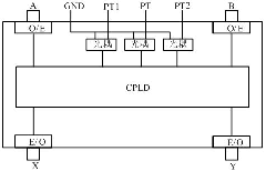
[0047] The steps of the single bus section or double bus voltage parallel method of the present invention are as follows:
[0048] Collect the voltage output of two sets of electronic voltage transformers on the two buses;
[0049] Use the position signals of the two isolated knife switches on the two buses as binary inputs, and collect the state signals of the two binary inputs;
[0050] Use the position signal of the isolation switch of the section switch or the bus tie switch as the binary input, and collect the status signal of the binary input;
[0051] According to the collected voltage output of the two sets of electronic voltage transformers, the status signal of the binary input of the two isolation switches and the status signal of the binary input of the isolation switch of the parallel switch, the voltage of each segment after parallel output is controlled;
[0052] As shown in Table 2 below, when it is collected that the parallel switch isolation swit...
PUM
 Abstract
Description
Claims
Application Information
 - R&D
- Intellectual Property
- Life Sciences
- Materials
- Tech Scout
- Unparalleled Data Quality
- Higher Quality Content
- 60% Fewer Hallucinations
Browse by: Latest US Patents, China's latest patents, Technical Efficacy Thesaurus, Application Domain, Technology Topic, Popular Technical Reports.
© 2025 PatSnap. All rights reserved.Legal|Privacy policy|Modern Slavery Act Transparency Statement|Sitemap|About US| Contact US: help@patsnap.com