Unlock instant, AI-driven research and patent intelligence for your innovation.

Control device, terminal device, and communication system

A technology of control devices and terminal devices, which is applied in the field of interference avoidance in wireless networks, and can solve problems such as increased power consumption, inability to communicate, and increased communication delays

Inactive Publication Date: 2010-08-11
SOVEREIGN PEAK VENTURES LLC
View PDF4 Cites 6 Cited by
  • Summary
  • Abstract
  • Description
  • Claims
  • Application Information

AI Technical Summary

Problems solved by technology

[0021] However, in order to change the frequency channel, it is necessary to search for a frequency channel with little influence of interference on both the side of the control device 701 and the side of the terminal devices 702-704, and search for a new frequency channel In the process of the channel, communication is not possible, and because it cannot enter the sleep state, there are problems of increased communication delay and increased power consumption

Method used


Image

  • Control device, terminal device, and communication system
  • Control device, terminal device, and communication system
  • Control device, terminal device, and communication system

Examples


Embodiment approach 1

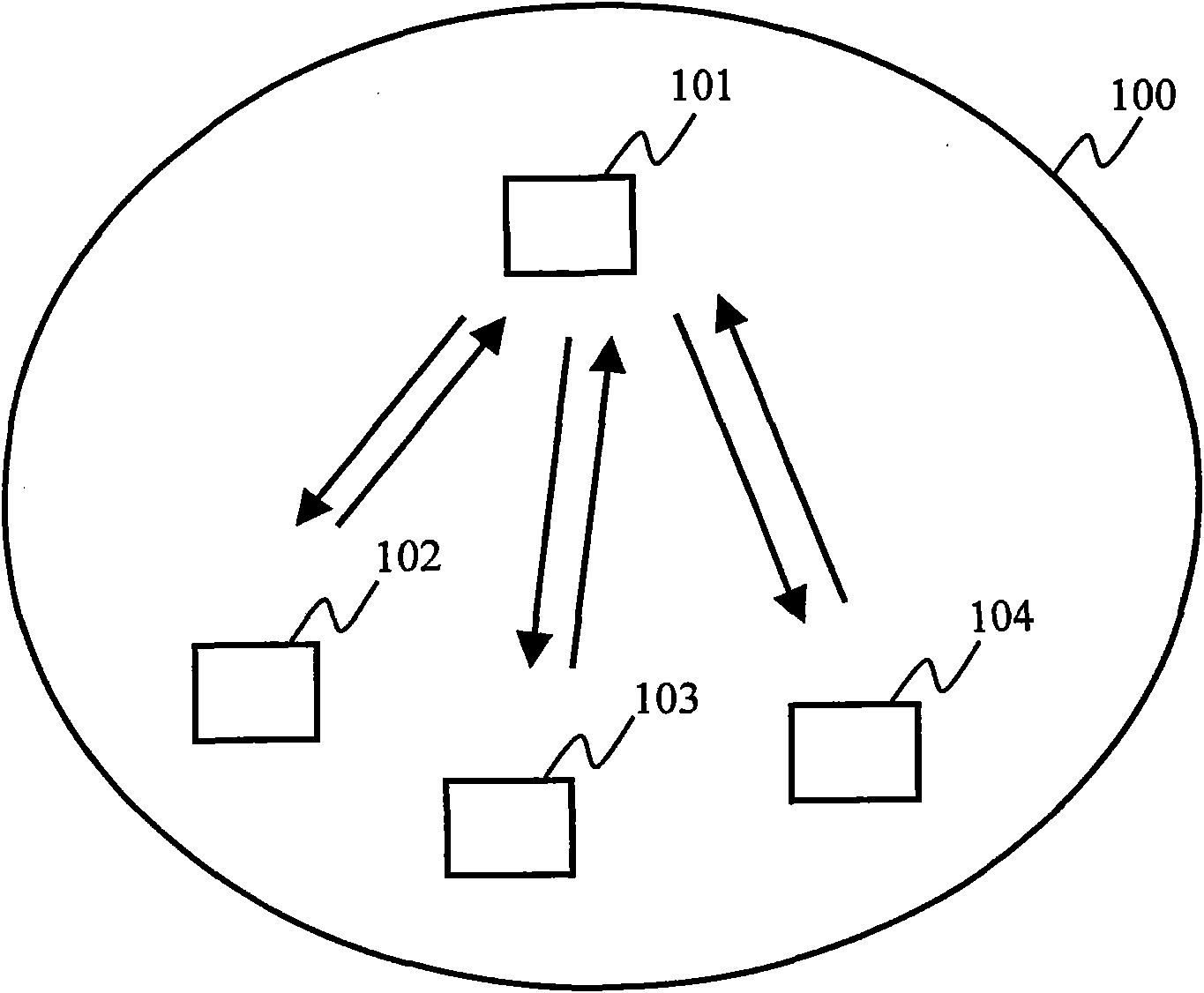
[0065] figure 1 It is a diagram showing an example of the configuration of the wireless network 100 in Embodiment 1 of the present invention. figure 1 In this example, a wireless network 100 includes a control device 101 and terminal devices 102-104. The number of terminal devices 102 to 104 may be any number as long as it is one or more. The control device 101 is a wireless terminal that controls communication in the wireless network 100 . The terminal devices 102 to 104 are wireless terminals that perform wireless communication with the control device 101 under the control of the control device 101 . In addition, a configuration in which the control device 101 and the terminal devices 102 to 104 are combined may be described as a communication system.

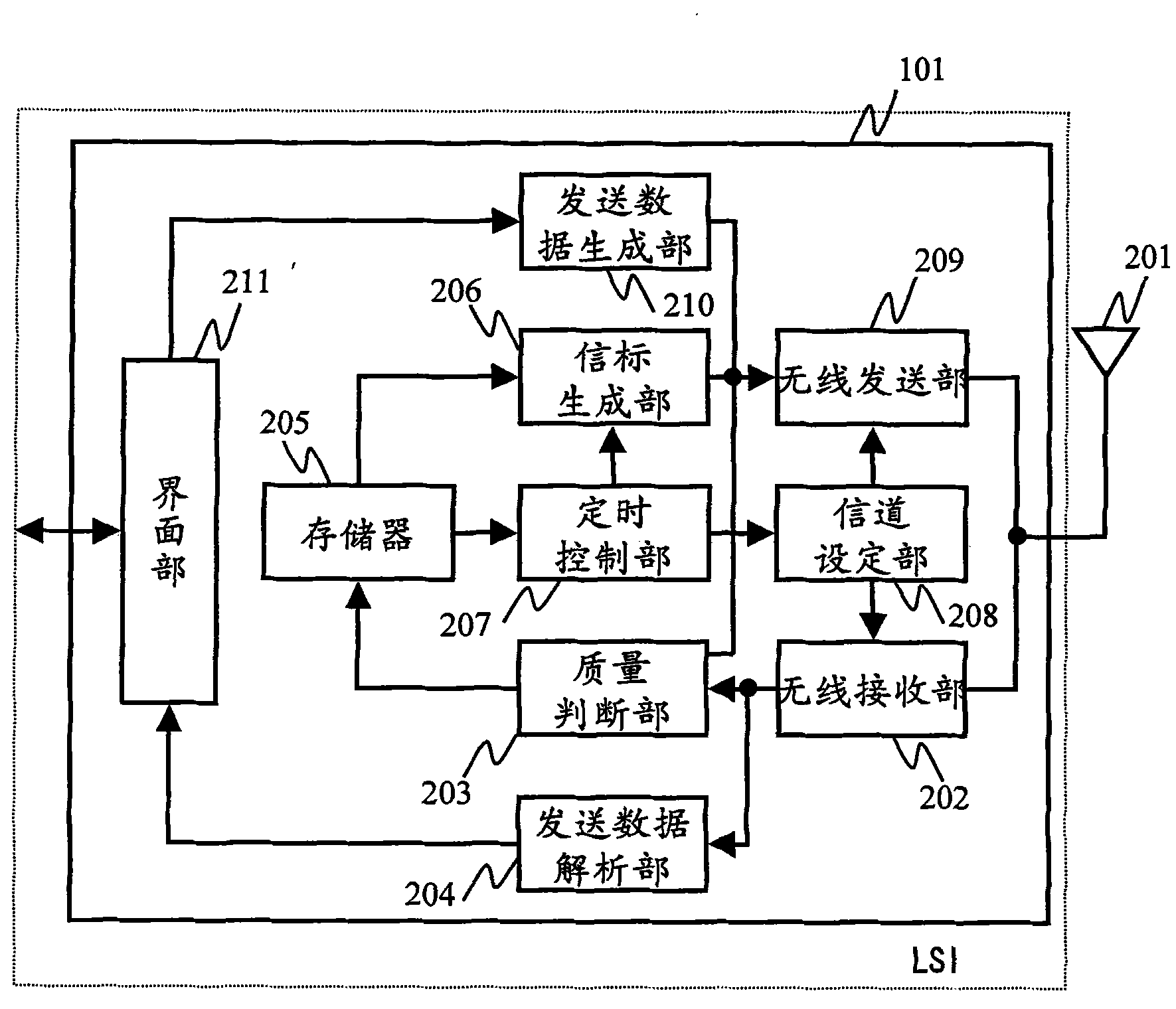
[0066] figure 2 It is a block diagram showing an example of the configuration of the control device 101 in Embodiment 1 of the present invention. figure 2 Among them, the control device 101 has: an antenna 201, a wir...

Embodiment approach 2

[0113] Figure 21 It is a figure which shows an example of the process flow of the data receiving process in the control apparatus 101 in Embodiment 2 of this invention. Other processing of the control device 101 is the same as the processing flow in Embodiment 1 of the present invention, and Figure 15 and Figure 16 The processing flow shown performs the same processing, and only the data reception processing in step S1015 is different.

[0114] Figure 21 Among them, if the control device 101 receives a frame from the terminal devices 102 to 104 in step S1031, it judges whether or not it is a data frame. When the received frame is not a data frame, the control device 101 proceeds to step S1032 to process other frames and end the process. When the received frame is a data frame, go to step S1033. Here, when the terminal apparatuses 102 to 104 have already switched the frequency channel from the previous beacon period, this information is described in the MAC header of t...

Embodiment approach 3

[0120] Figure 22 It is a figure showing the structure of the superframe period in Embodiment 3 of this invention. Figure 22 , the superframe period and the beacon period are the same as those used in Embodiment 1 of the present invention Figure 5 The explained superframe period and beacon period are the same, and their explanations are omitted.


PUM


Abstract

Provided is a radio network which uses a plurality of channels and performs a radio communication exhibiting an excellent latency and power saving property while avoiding the affect of an interference wave. A control device (101) performs channel switching for each beacon period to transmit a beacon frame and communicate with radio terminals (102 to 104). The control device (101) measures a channel communication state and presence / absence of affects of an interference wave so as to judge whether a channel can be used, and stores the usable channel information. The control device (101) distributes the usable channel information to the terminal devices (102 to 104) using a beacon frame. The terminal devices (102 to 104) perform a radio communication by switching the channels from one to another so as to select an optimal channel for each beacon period in accordance with the usable channel information relating to the received beacon frame and the transmission state of the channel used bythe local station. Thus, it is possible to perform use channel switching at a high speed while avoiding the affects of the interference wave.

Description

technical field [0001] The present invention relates to a control device, a terminal device, a communication system, and a communication method used in a wireless network, and particularly relates to the method of avoiding interference in a wireless network that accommodates a plurality of wireless terminals such as a sensor network and an active radio frequency (RF: Radio Frequency) tag. technology. Background technique [0002] In recent years, networks formed using small and low-power-consumption wireless terminals such as wireless personal area networks (WPAN:Wireless Personal Area Network) and sensor networks have attracted attention. Also, as a system similar thereto, there is a system such as an active RF tag which itself transmits a wireless signal. [0003] Figure 24 It is a diagram showing an example of the configuration of a conventional wireless network 700 . Figure 24 In the prior art, a wireless network 700 includes a control device 701 and a plurality of te...

Claims


Application Information

Patent Timeline
IPC IPC(8): H04W72/02H04W84/10
CPCH04W72/082H04W52/0238H04W72/02H04W52/0216Y02B60/50H04W72/042H04B1/713Y02D30/70H04W72/541H04W72/23
Inventor 林野裕司太田良隆
Owner SOVEREIGN PEAK VENTURES LLC