
Side vehicle-body structure of automotive vehicle

A vehicle side and body technology, which is applied to the superstructure, superstructure sub-assemblies, vehicle components, etc., can solve problems such as restricting design freedom, increasing body weight, and increasing assembly processes, ensuring design freedom and improving appearance. sexual effect

Inactive Publication Date: 2010-08-18
MAZDA MOTOR CORP
View PDF4 Cites 16 Cited by
  • Summary
  • Abstract
  • Description
  • Claims
  • Application Information

AI Technical Summary

Problems solved by technology

[0004] First, when a bulge is formed on the side sill outer part and protrudes greatly outward in the vehicle width direction, the portion of the steel plate is greatly increased, which increases the weight of the vehicle body
The increase in body weight will also lead to an increase in cost
Second, there are problems in the formability of the body
[0009] The structure of the above-mentioned patent document can shorten the lower part of the side sill outer part so that the side sill outer part can be arranged close to the upper side of the side sill, but it cannot obtain a sufficiently large degree of freedom in design.
That is, in order to hide the junction between the lower end of the side sill outer and the side sill reinforcement, it is necessary to arrange the junction by extending the lower end of the side sill outer downward or extending the side portion of the side sill trim member upward. On the inner side of the side sill trim member, thus limiting design freedom
[0010] In addition, when installing the side sill trim member, it is necessary to design the side sill trim member separately and increase the assembly process separately, so there is also a problem in terms of cost other than the material cost
In addition, although the side sill decorative member can improve the appearance, it does not contribute to the improvement of the rigidity of the vehicle body in terms of improving the safety that is a basic requirement of the vehicle.

Method used


Image

  • Side vehicle-body structure of automotive vehicle
  • Side vehicle-body structure of automotive vehicle
  • Side vehicle-body structure of automotive vehicle

Examples


Embodiment 1

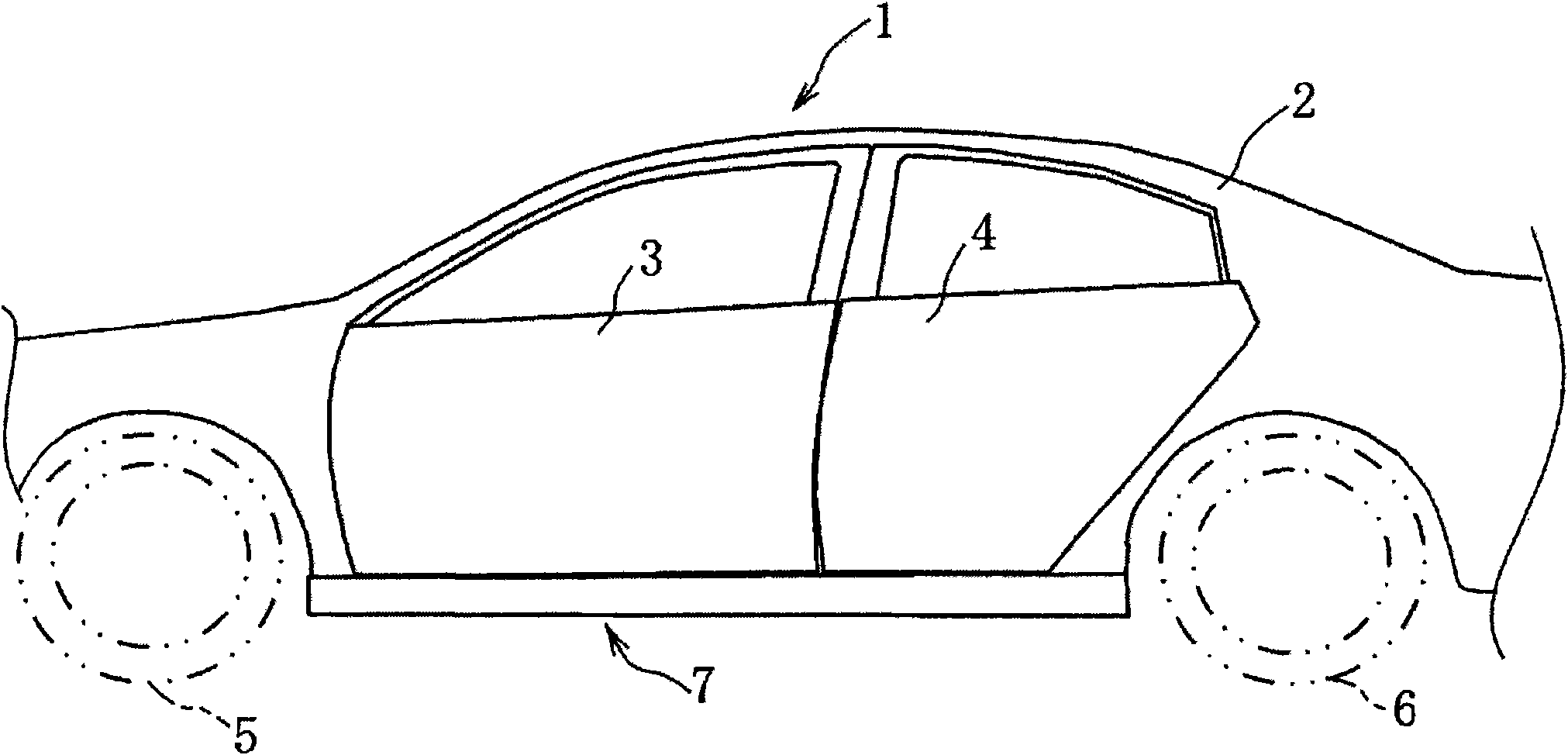
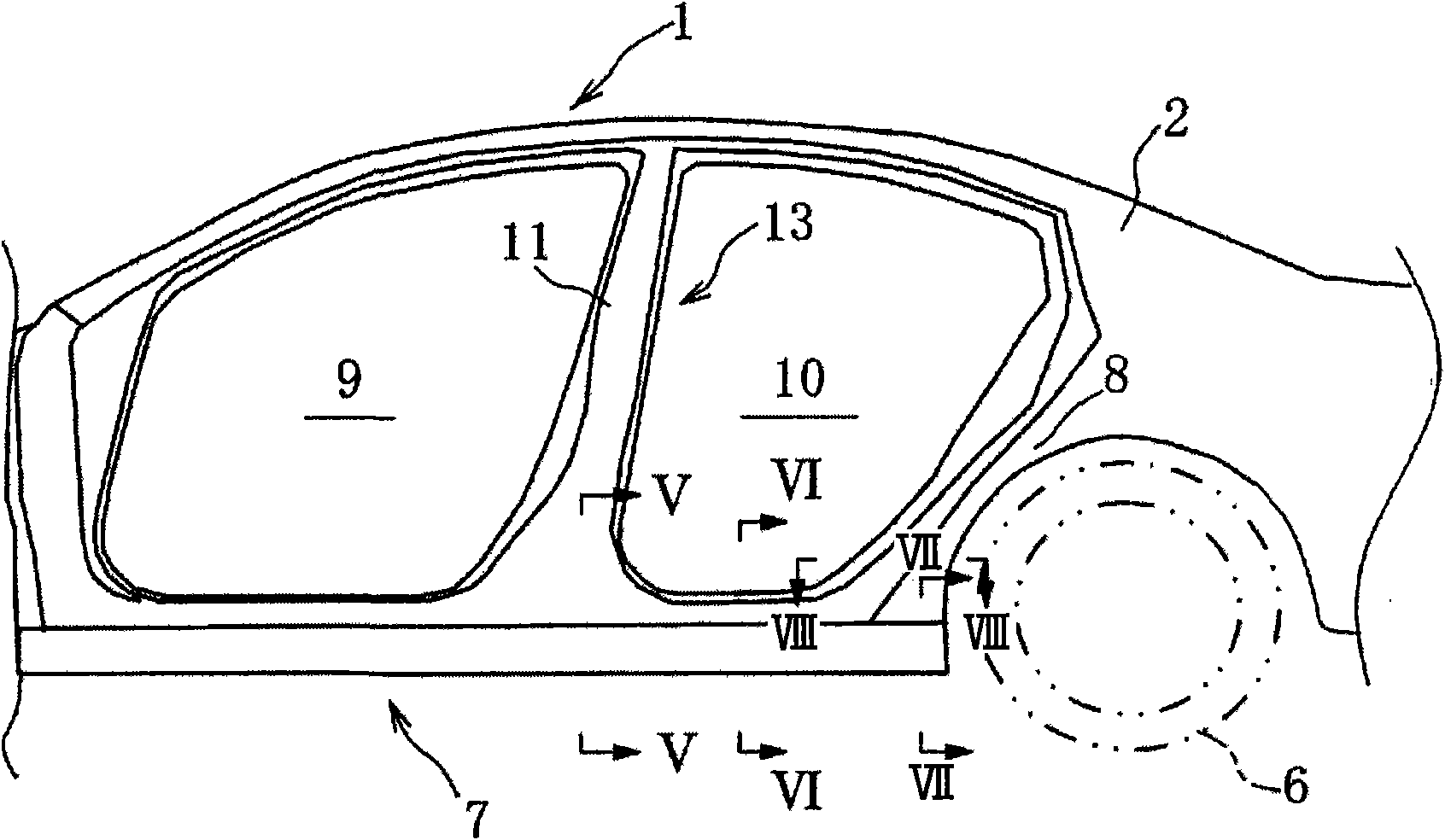
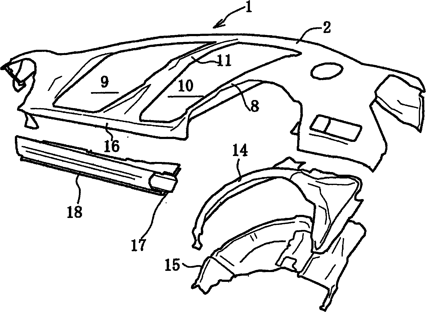
[0053] Next, Embodiment 1 of the present invention will be described with reference to the drawings. figure 1 It is a side view showing the side body structure of the automobile involved in Example 1; figure 2 is a side view showing the side body structure with the side door removed; image 3 yes figure 2 An exploded view of the side body structure shown; Figure 4 It is a perspective view of main parts of the side body structure.

[0054] Such as figure 1 As shown, the vehicle 1 related to Embodiment 1 is a 4-door passenger car, and a side panel 2 (side body outer panel), a front door 3, a rear door 4, a front wheel 5, and a rear wheel 6 are provided on the side of the vehicle body. . Below the front door 3 and the rear door 4 is provided a long side sill 7 extending in the front-rear direction of the vehicle body. The side sill 7 is connected to the side panel 2 as a frame member of the vehicle 1 .

[0055] Such as figure 2 As shown, the side wall outer part 2 ha...

Embodiment 2

[0084] Next, according to Figure 9 ~ Figure 11 Example 2 will be described. However, the same symbols are assigned to the same structures as in Example 1. FIG. in addition, Figure 10 Indicates equivalent to that of Example 1 Figure 7 cutaway view.

[0085] The wheel house arch portion 8 includes a wheel house outer 14 located on the outside in the vehicle width direction, and a wheel house inner 15 located on the inside in the vehicle width direction. The left and right ends and the upper end of the wheel house outer 14 are overlapped with the left and right ends and the upper end of the wheel house inner 15 , and a storage space for the rear wheel 6 is formed in the central region.

[0086] Such as Figure 10 As shown, the side sill outer part 16 and the side sill reinforcement 18 extend rearwardly in the rear region of the vehicle body. The rear end region of the side sill reinforcement 18 is in contact with the wheel house arch portion 8 , and the second upper flan...

Embodiment 3

[0096] Next, according to Figure 12 Example 3 will be described. However, the same symbols are assigned to the same structures as in Example 1. FIG. in addition, Figure 12 Indicates equivalent to that of Example 1 Figure 6 cutaway view.

[0097] The side sill 7 connected to the side sill outer 2 includes a side sill outer 16 constituted by the lower portion of the side sill outer 2 , a side sill inner 17 located inside the side sill outer 16 in the vehicle width direction, and a side sill The reinforcement 18 and the side sill trim member 26 made of resin mounted on the outside of the side sill reinforcement 18 in the vehicle width direction.

[0098] The side sill reinforcement 18 protruding outward in the vehicle width direction with a substantially hat-shaped cross section is disposed on the side sill inner 17 protruding inward in the vehicle width direction with a substantially hat-shaped cross section, and on the outer side of the side sill inner 17 in the vehicle ...


PUM


Abstract

A second closed cross section which projects toward the outside from a third lower flange of a side sill outer and a lower end portion is provided. Lower cross sections of the third lower flange and the lower end portion contact a second upper wall portion. The second closed cross section and a third closed cross section are formed by a side sill reinforcement of a frame member of a vehicle body.Thereby, a split line can be made be recognized as on body with the second closed cross section, so that both increasing the vehicle-body rigidity and improving the exterior appearance can be achieved.

Description

technical field [0001] The present invention relates to the structure of the side body of an automobile, and more particularly to the structure of a side sill connected to a side outer panel forming the lower surface of the vehicle body. Background technique [0002] In an automobile, a side sill extending in the front-rear direction of the vehicle body is provided below the left and right side surfaces of the vehicle body. The side sill is intended to maintain the rigidity of the lower part of the vehicle body and reduce the weight of the vehicle body. The side sill inner part in the vehicle width direction and the side sill outer part outside in the vehicle width direction have a closed cross-sectional structure. [0003] In recent years, there has been known a structure in which the appearance volume of the lower part of the vehicle body is increased for the purpose of visually stabilizing the side of the vehicle body and improving the appearance. In order to improve suc...

Claims


Application Information

Patent Timeline
Patent Type & Authority Applications(China)
IPC IPC(8): B62D25/02B62D25/16
CPCB62D25/02B62D25/025B62D25/2036
Inventor 福岛嘉男
Owner MAZDA MOTOR CORP
Learn More