
Monitor and rubber frame

A display and plastic frame technology, applied in the direction of instruments, nonlinear optics, optics, etc., can solve problems such as panel damage, and achieve the effect of avoiding damage

Inactive Publication Date: 2012-07-04
AU OPTRONICS CORP
View PDF0 Cites 0 Cited by
  • Summary
  • Abstract
  • Description
  • Claims
  • Application Information

AI Technical Summary

Problems solved by technology

[0004] The technical problem to be solved by the present invention is to provide a display and its plastic frame to solve the problem of moisture seeping into the display panel and causing damage to the panel
The bearing surface is used to bear the display panel

Method used


Image

  • Monitor and rubber frame
  • Monitor and rubber frame
  • Monitor and rubber frame

Examples


Embodiment Construction

[0034] The display and its plastic frame according to the embodiments of the present invention use one or more perforated structures as drainage paths to guide condensed water away from between the plastic frame and the display panel. The following describes a display according to an embodiment of the present invention.

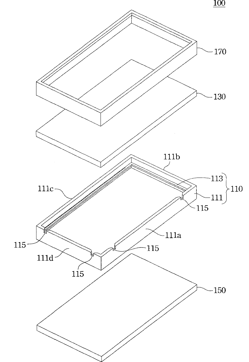
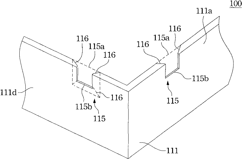
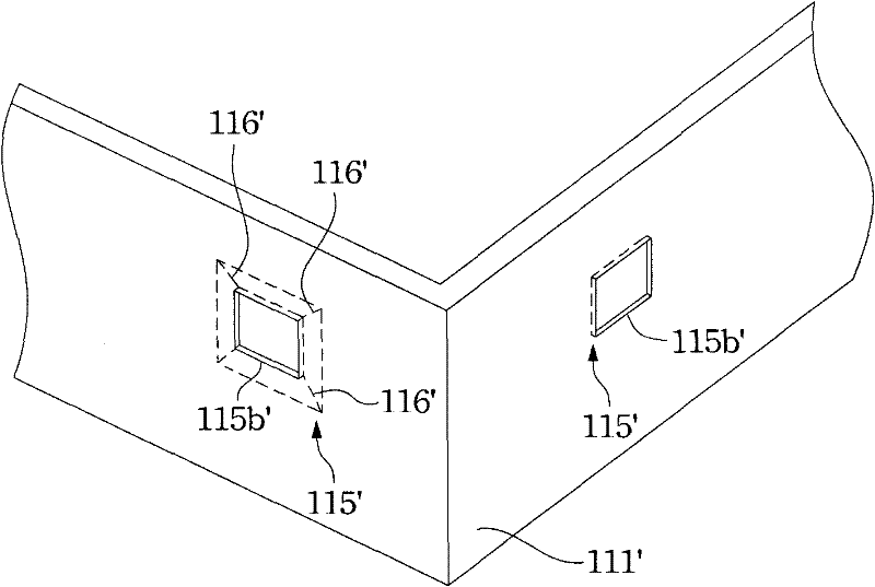
[0035] Please also refer to figure 1 and figure 2 , figure 1 An exploded view showing a display according to an embodiment of the present invention, figure 2 draw figure 1 Partially enlarged schematic diagram of the middle plastic frame. The display 100 includes a display panel 130 , a plastic frame 110 and a front frame 170 . The plastic frame 110 includes a side wall 111 and a supporting surface 113 , the side wall 111 surrounds the periphery of the display panel 130 and has a perforation structure 115 . The supporting surface 113 is used for supporting the display panel 130 . The front frame body 170 covers the display panel 130 to fix the display...


PUM


Abstract

The invention discloses a monitor and a rubber frame. The monitor at least comprises a display panel, the rubber frame, a backlight module and a front frame body, wherein the display panel and the backlight module are separately arranged on the opposite surfaces of the rubber frame; the rubber frame contains a side wall and a holding surface, the holding surface is used to hold the display panel,the side wall has a punching structure which is arranged on at least one side of the side wall; and the front frame body is covered on the display panel for fixing the display panel and the backlightmodule.

Description

technical field [0001] The invention relates to an electronic device and its fixing structure, and in particular to a display and its plastic frame. Background technique [0002] With the advancement of technology, flat panel displays have replaced traditional cathode ray tube displays and become the mainstream of the market due to their advantages of thinness, lightness, power saving, and low radiation. Whether it is audio-visual use in general households, commercial use in business premises, industrial research and production use, or even outdoor large-scale public display use, flat-panel displays have filled the daily lives of modern people. [0003] As the application fields of flat-panel displays become wider and wider, the displays also need to face more and more diverse usage environments. For example, if it is used in an environment with high humidity and large temperature changes, it is prone to condensation of water vapor. Dew often accumulates between the displa...

Claims


Application Information

Patent Timeline
Patent Type & Authority Patents(China)
IPC IPC(8): G02F1/13
Inventor 吴居郇邱振铭卢芳志沈文斌
Owner AU OPTRONICS CORP
Learn More