Power connectors with contact-retention features

A technology of power contacts and contact beams, which is applied in the direction of connections, components of connection devices, circuits, etc., and can solve the problems of increased size and manufacturing costs

Inactive Publication Date: 2010-08-18
FRAMATOME CONNECTORS INT SA
View PDF0 Cites 0 Cited by
  • Summary
  • Abstract
  • Description
  • Claims
  • Application Information

AI Technical Summary

Problems solved by technology

Increased size and conductive material often results in increased manufacturing costs

Method used


Image

  • Power connectors with contact-retention features
  • Power connectors with contact-retention features
  • Power connectors with contact-retention features

Examples


Embodiment Construction

[0019] In the following introduction certain terms are used for convenience only and should not be considered limiting in any way. For example, the terms "top", "bottom", "left", "right", "upper", and "lower" in the drawings denote directions to a referenced object. Likewise, the terms "inwardly", "outwardly", "upwardly", and "downwardly" may refer to directions toward and away from, respectively, the geometric center of a reference object. Terminology includes the words specified above, their derivatives, and words of similar meaning.

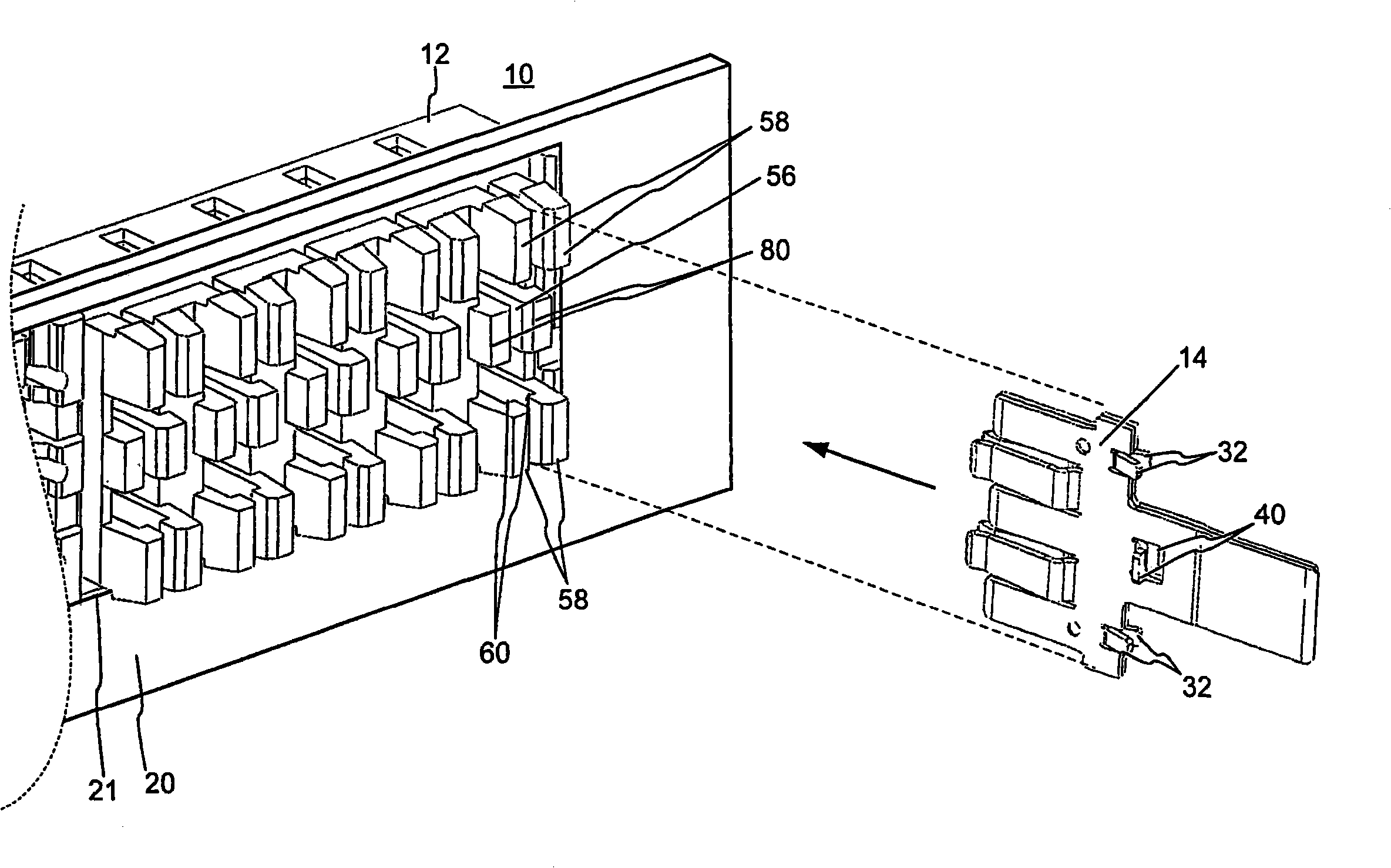
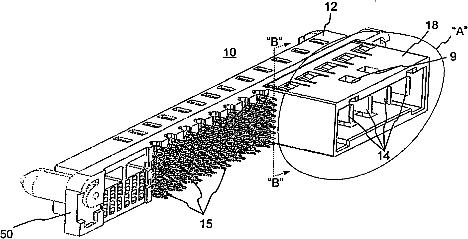
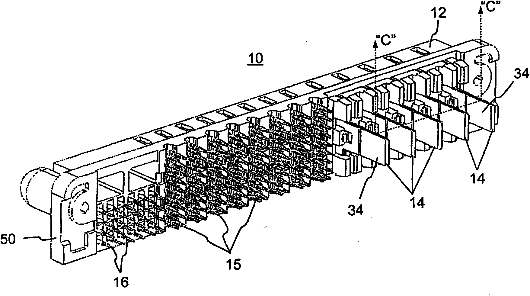
[0020] 1 and 2 show top rear perspective views of the connector 10, with and without the shroud 18, respectively. The electrical connector 10 may provide electrical connections for data transmission signals and electrical power, ie, alternating current (AC) power and / or direct current (DC) power.

[0021] The electrical connector 10 may include a housing 12 , power contacts 14 for AC power, power contacts 15 for DC power, signal contacts 16 ...


PUM


Abstract

A power receptacle contact may include first and second contact beams that deflect independently of one another during mating of the power receptacle contact with a complementary blade contact. Each beam may extend from abutting respective body portions. The power receptacle contact may include a first clip that extends from the first contact beam. The first clip may define a blade receiving area between the first and second contact beams. A power connector may include a housing and a contact received in the housing. The contact may includes first and second protrusions that prevent the contact from moving in a first direction relative to the housing and in a second direction opposite the first direction.

Description

technical field [0001] The present invention relates to power contacts and power connectors having contact retention features. Background technique [0002] Connectors for transmitting electrical power, such as alternating current (AC) power and / or direct current (DC) power, may include power contacts mounted within an electrically insulating housing. In a typical application, the connector may be mounted to a substrate, such as a circuit board, and the connector may be configured to mate with a corresponding power cable assembly. In particular, each power contact within the housing may include one or more male contact beams and / or female receptacles that mate with opposite sex components within the power cable assembly. [0003] Actual forces are exerted on the individual power contacts inside the cable assembly and inside the installed connector during detachment and mating of the cable assembly with the installed connector. These forces may drive the power contacts out ...

Claims


Application Information

Patent Timeline
IPC IPC(8): H01R13/42
CPCH01R13/112H01R13/432
Inventor H·恩戈T·W·胡兹
Owner FRAMATOME CONNECTORS INT SA
Why Eureka
Try Eureka