
Method and device in telecommunication system

A telecommunications system and channel technology, applied in baseband systems, transmission systems, digital transmission systems, etc., can solve problems such as inability to quickly detect radio links, insufficient measurement opportunities, etc., to achieve fast and reliable radio problem detection, fast Effect of changing, short switching delay

Active Publication Date: 2017-01-18
TELEFON AB LM ERICSSON (PUBL)
View PDF7 Cites 0 Cited by
  • Summary
  • Abstract
  • Description
  • Claims
  • Application Information

AI Technical Summary

Problems solved by technology

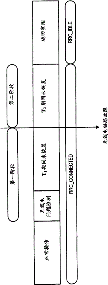
Due to insufficient measurement opportunities in DRX mode (depending on DRX cycle), UE will not be able to detect radio link problems quickly

Method used


Image

  • Method and device in telecommunication system
  • Method and device in telecommunication system
  • Method and device in telecommunication system

Examples


Embodiment Construction

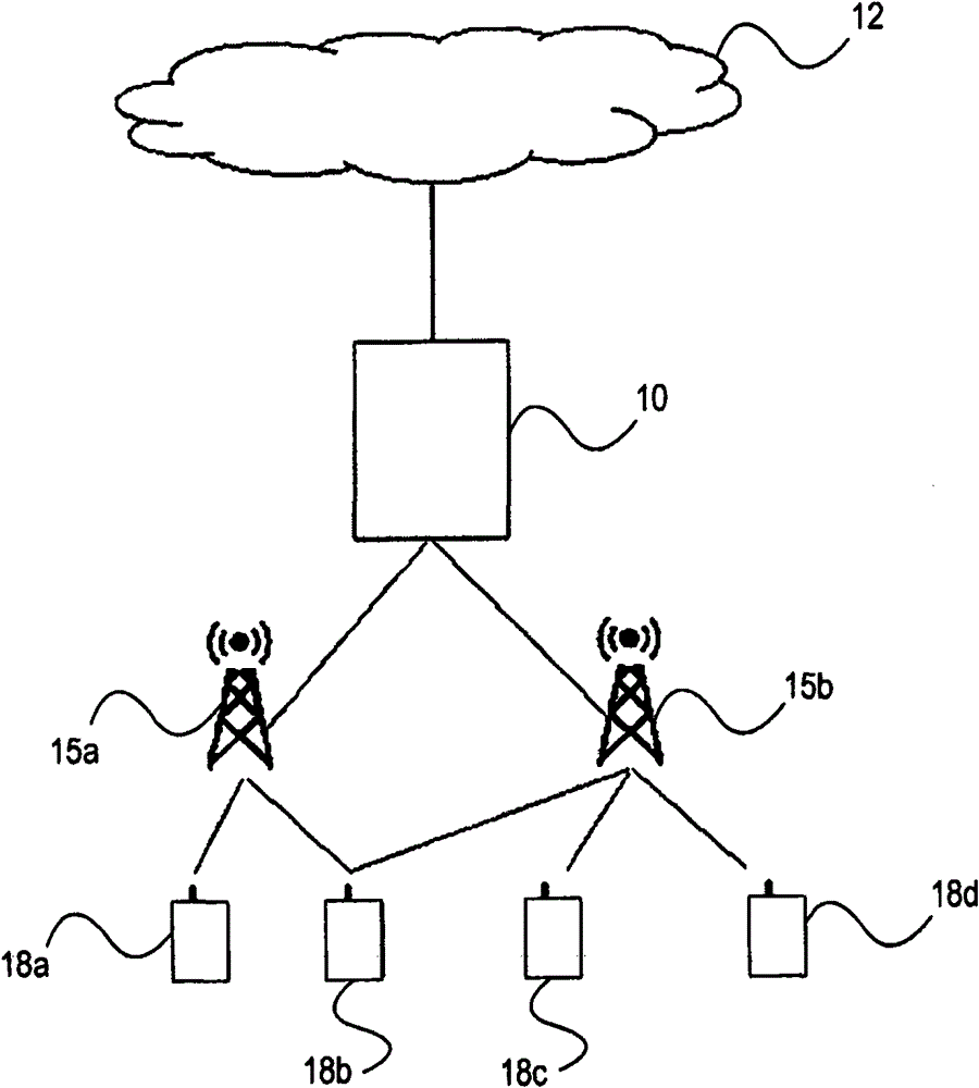
[0059] figure 1 A communication system, such as an OFDM system or a WCDMA system, is described comprising a Radio Access Network (RAN) (such as the Evolved UMTS Terrestrial Radio Access Network (E-UTRAN) architecture) comprising at least one Radio Base Station (RBS) ( or Node B) 15a-b, connected to one or more Radio Network Controllers (RNC) 10( figure 2 only one is shown). The RAN is connected via an interface such as an lu interface to a core network (CN) 12, which may be a connection-oriented external CN (such as a public switched telephone network (PSTN) or an integrated services digital network (ISDN)), and / or Or no connection to external CN (eg Internet).

[0060] The RAN and CN 12 provide communication and control for a plurality of user equipments (UEs) 18a-d. UEs 18 each communicate with at least one RBS 15 via a radio or air interface using a downlink (DL) channel (i.e., base station to user or forward) and an uplink (UL) channel (i.e., user to base station or re...


PUM


Abstract

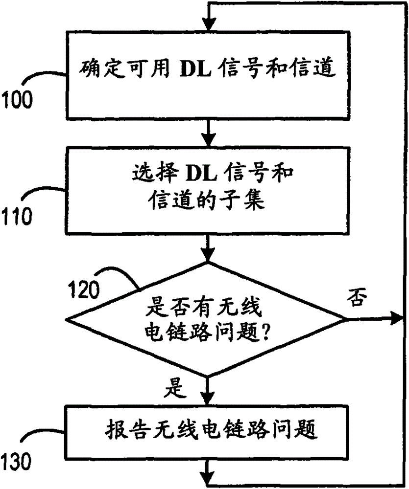
A user equipment in a cellular telecommunication system having multiple downlink physical channels detects radio link problems using a subset of said physical channels, wherein said subset can be dynamically adjusted according to which channels are available at a particular instant.

Description

technical field [0001] The present invention relates to the detection of downlink radio link problems. Background technique [0002] Radio link monitoring is crucial to maintaining radio connections in cellular systems. By regularly reporting radio conditions to the system, various types of actions can be taken when a radio link failure occurs. [0003] In UTRA, the physical layer estimates the quality of the radio link and reports the synchronization status to higher layers based on radio frames via so-called synchronization primitives, such as 3GPP TS 25.214V7.4.0 "Physical layer procedures (FDD) ("Physical layer procedures (FDD )") as described in). [0004] There will also be a need to report radio link quality status in E-UTRA, where it is beneficial to detect radio problems quickly and reliably, thereby avoiding unnecessary interference in the uplink, wasting resources in the downlink and enabling Unnecessarily long delays before cell reselection or handover. [00...

Claims


Application Information

Patent Timeline
Patent Type & Authority Patents(China)
IPC IPC(8): H04L1/20H04W36/30
CPCH04L1/0061H04L1/1829H04L1/20H04L25/0224H04W36/30H04W76/28H04W72/542H04W24/08H04W24/10H04W28/04H04L43/16H04L43/0823
Inventor L·林德博姆J·M·伯格曼D·格斯滕伯格M·A·卡兹米
Owner TELEFON AB LM ERICSSON (PUBL)
Learn More