
Plug pin formed using an extrusion process

A technology of plug pins and extrusion molding, which is applied to the connection of permanent deformation, the parts of the connection device, and the manufacture of contact pieces, which can solve the problems of inapplicability and achieve the effect of saving price and saving transportation weight

Inactive Publication Date: 2013-01-30
迈克尔·塔勒尔
View PDF3 Cites 0 Cited by
  • Summary
  • Abstract
  • Description
  • Claims
  • Application Information

AI Technical Summary

Problems solved by technology

Spring ends shown are not suitable for power plugs

Method used


Image

  • Plug pin formed using an extrusion process
  • Plug pin formed using an extrusion process
  • Plug pin formed using an extrusion process

Examples


Embodiment Construction

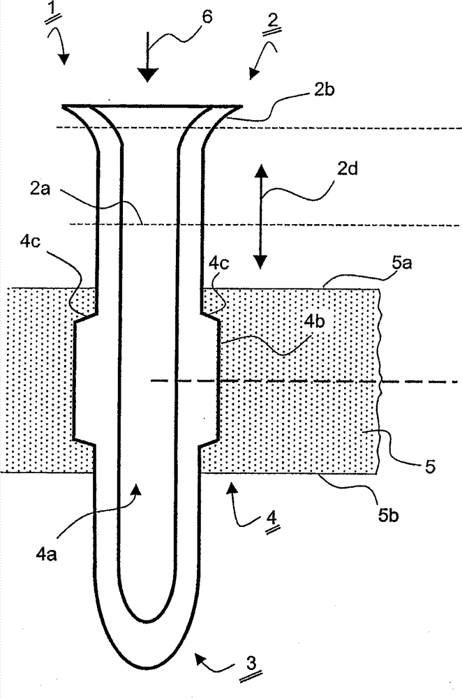
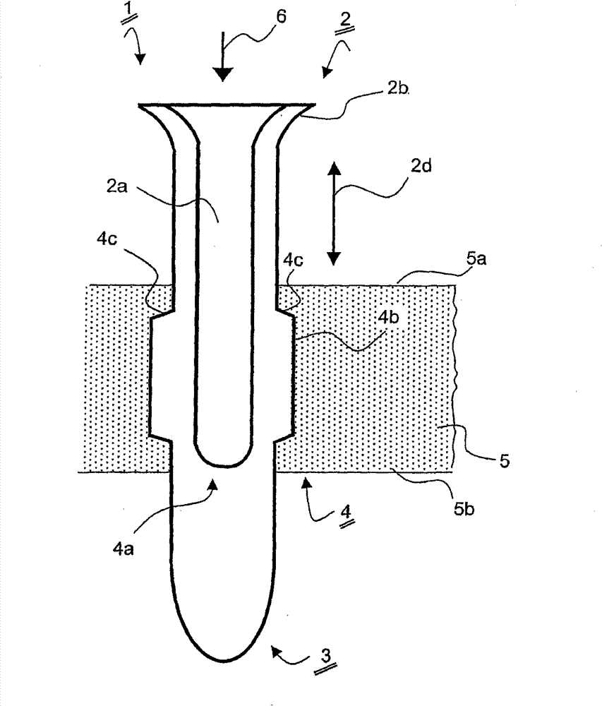
[0035] according to Figure 1a , the plug pin generally denoted by 1 comprises a connection end 2 for connecting a not shown power supply stranded wire, and an extruded central area 4 leading from the connection end 2 to the contact end 3 on the socket side, wherein , the central region 4 is hollow, as indicated by the cavity 4a, and the connection end 2 is formed as a clamping end 2a.

[0036] The plug pins 1 are used in this example for a double-secured plug and are injected into a plug bridge base 5 made of plastic during use. The plug pins are made of a specially conductive material, preferably brass which can be used here. The availability of other metals, particularly stainless steel, has been thoroughly described and published.

[0037] A funnel-shaped extension 2b is provided on the connection end 2, which makes it easier to push in the power supply strands, for example from the direction indicated by the arrow 6, without the strands affecting the safety of the finish...


PUM


Abstract

The invention relates to a plug pin having a connection end for connection to a supply system connection wire and having a central region which is formed by extrusion shaping and leads from the connection end to a contact end on the socket contact. In this case, provision is made for the connection end to be in the form of a crimped end and for the central region to be hollow.

Description

technical field [0001] The invention relates to a plug pin as well as its production and application. Background technique [0002] Plug pins are well known. It is applied to the power plug of electrical appliances to realize the connection between the conductive twisted wires of the power cord as a conductive connection in the socket. [0003] For this purpose, the plug pins are typically fastened in a plug bridge in which the plug pins are enclosed in a non-conductive plastic with a geometrically correct mutual spacing and with the correct protrusion height. Plug bridges can have ground spring clips and in some applications filter elements or similar. When producing the power cord applied to the plug bridge, the insulation layer of the twisted wire of the power cord is removed at first, and then fixedly connected to the connecting end of the plug pin. After fixing the strands, a PVC insert, typically produced by the injection molding method, is formed around the connect...

Claims


Application Information

Patent Timeline
Patent Type & Authority Patents(China)
IPC IPC(8): H01R43/16H01R4/18H01R13/04H01R13/405
CPCH01R13/405H01R43/16H01R4/183H01R13/04
Inventor 迈克尔・塔勒尔
Owner 迈克尔·塔勒尔
Learn More