Sealing ring

A sealing ring, annular technology, applied in the direction of engine sealing, mechanical equipment, engine components, etc., can solve problems such as affecting the sealing effect, and achieve the effect of good sealing effect

Active Publication Date: 2010-09-08
JIANGSU DAQO CHANGJIANG ELECTRICAL +2
View PDF6 Cites 7 Cited by
  • Summary
  • Abstract
  • Description
  • Claims
  • Application Information

AI Technical Summary

Problems solved by technology

When the ordinary O-ring is used, the gas on the side with higher air pressure will overcome the material elasticity of the sealing ring under the action of pressure and leak from the contact part between the sealing ring and the sealing surface to the low-pressure side, and the greater the pressure difference between the inside and the outside, The stronger the tendency of this leakage, thus affecting the sealing effect

Method used


Image

  • Sealing ring
  • Sealing ring
  • Sealing ring

Examples


Embodiment Construction

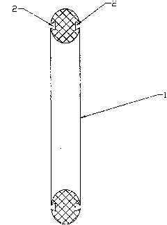
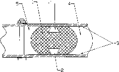
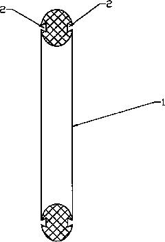
[0009] As shown in the figure, the sealing ring has an O-shaped annular base 1 with an O-shaped cross-section, and annular grooves 2 are respectively opened on the front and rear end faces of the annular base. The cross-sectional shape of the groove is narrow at the mouth and narrow at the bottom wide trapezoid.

[0010] During use, the front and rear end surfaces of the sealing ring are respectively pressed on the two sealing contact surfaces 3 that need to be sealed and connected, and the groove 2 forms a closed cavity. When the gas on the high-pressure side 4 leaks to the low-pressure side 5, it first enters the groove 2 Constitutes a closed cavity, with the increase of gas in the closed cavity, the pressure in it is also increasing, because it is a trapezoidal structure, the pressure generated by the pressure acts on the two sides of the trapezoid, and the vertical component force generated by it makes The base material of the sealing ring fits more closely with the contac...


PUM


Abstract

The invention relates to a sealing ring for performing inner and outer sealing on a joint face. The sealing ring has an annular basal body with an O-shaped cross section, and annular grooves are respectively arranged on the front and rear end surfaces of the annular basal body, and the cross sections of the grooves are in a ladder shape with a narrower mouth part and a wider bottom part. When in use, as gas at the high pressure side of the sealing ring leaks to the lower pressure side of the sealing ring, the sealing ring basal body material expands outwards and is presses on the contact surface more tightly, so the larger the inner pressure is, the larger the pressure applied on the contact surface by the sealing ring basal body material is, thus ensuring better sealing effect.

Description

technical field [0001] The invention relates to a sealing ring used for internal and external sealing of connecting surfaces. Background technique [0002] In existing gas-insulated switchgear and other devices with airtight requirements, O-rings are often used for sealing the mounting surfaces of plane connections. When the ordinary O-ring is in use, the gas on the side with higher air pressure will overcome the material elasticity of the sealing ring under pressure and leak from the contact part between the sealing ring and the sealing surface to the low-pressure side, and the greater the pressure difference between the inside and the outside, The stronger the tendency of this leakage, thus affecting the sealing effect. Contents of the invention [0003] The technical problem solved by the invention is: on the basis of the existing O-shaped sealing ring structure, provide a sealing ring with good sealing effect. [0004] The technical solution of the present invention ...

Claims


Application Information

Patent Timeline
IPC IPC(8): F16J15/06
Inventor 裴军戴俊独田娃马永范孙华美李卫卫林永峰
Owner JIANGSU DAQO CHANGJIANG ELECTRICAL
Why Eureka
Try Eureka