Image shake correction apparatus and image pickup apparatus
An image pickup device and shake correction technology, which can be applied to projection devices, printing devices, image communication, etc., and can solve problems such as hindering the smooth moving operation of the holding member and immobility of the holding member
- Summary
- Abstract
- Description
- Claims
- Application Information
AI Technical Summary
Problems solved by technology
Method used
Image

Examples
no. 1 example
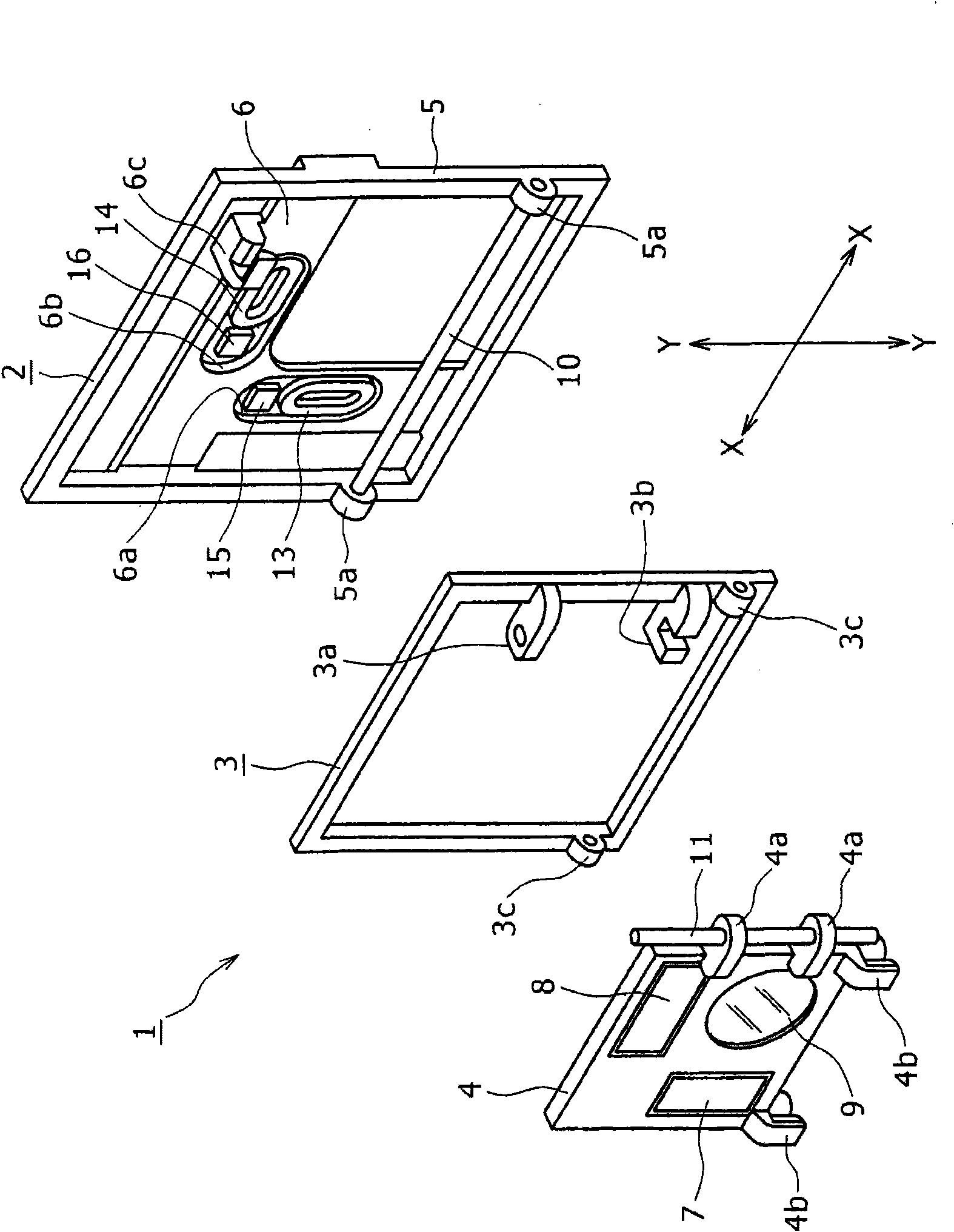
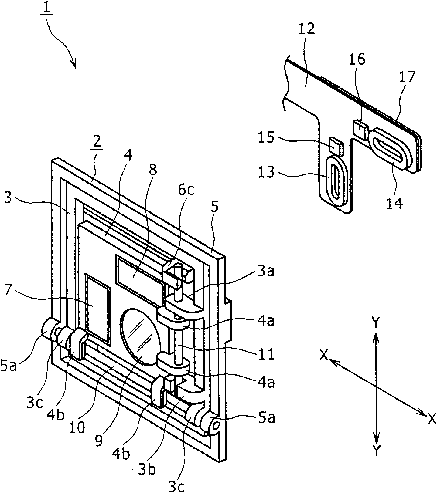
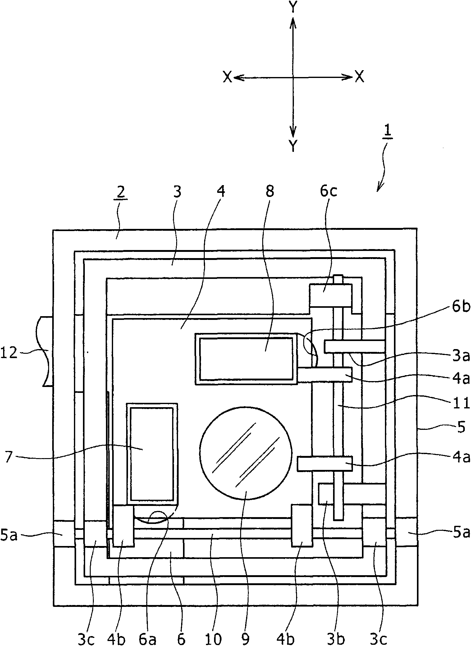
[0056] In the following, refer to Figures 1 to 9 An image shake correction device according to a first embodiment of the present invention will be described.
[0057] first reference Figures 1 to 3 , the image shake correction device 1 includes: a fixed member 2 , an intermediate member 3 and a movable member 4 .
[0058] The fixing member 2 includes a frame-like portion 5 formed like a rectangular frame and a mounting surface portion 6 provided on the inner side of the frame-like portion 5 . The fixing member 2 is fixed to, for example, a holding tube, which is not shown and provided as an outer housing of the lens barrel.
[0059] A pair of round bearing portions 5a are provided in a spaced relationship left and right from each other at a position near the lower end of the frame portion 5 of the fixing member 2 and protrude forward. A circular bearing hole is formed through each circular bearing portion 5a in the left-right direction.
[0060] The mounting surface port...
no. 2 example
[0089] In the following, refer to Figures 10 to 12 An image shake correction device according to a second embodiment of the present invention will be described.
[0090] The image shake correction device 51 includes a fixed member 52 , an intermediate member 53 and a movable member 54 .
[0091] The fixing member 52 includes a frame-like portion 55 formed like a rectangular frame and a mounting surface portion 56 provided inside the frame-like portion 55 . The fixing member 52 is fixed to, for example, a holding tube which is not shown and which is provided as an outer case of the lens barrel.
[0092] A pair of fixing pieces 57 are provided at positions near the left end of the fixing member 52 apart from each other in the up-down direction. A circular bearing hole is formed through each fixing piece 57 in the up-down direction. A pair of groove-shaped bearing portions 55 a are provided apart from each other in the left-right direction so as to open downward at positions ...
PUM
 Abstract
Description
Claims
Application Information
 - R&D
- Intellectual Property
- Life Sciences
- Materials
- Tech Scout
- Unparalleled Data Quality
- Higher Quality Content
- 60% Fewer Hallucinations
Browse by: Latest US Patents, China's latest patents, Technical Efficacy Thesaurus, Application Domain, Technology Topic, Popular Technical Reports.
© 2025 PatSnap. All rights reserved.Legal|Privacy policy|Modern Slavery Act Transparency Statement|Sitemap|About US| Contact US: help@patsnap.com