Structure of supporting core assembly and bearing for a bldc

A brushed DC motor and bearing support technology is applied to electric components, casings/covers/supports, electrical components, etc., and can solve problems such as the expansion of the inner diameter of the core component 100, the reduction of the length direction of the core 110, and the increase of materials and assembly costs. , to achieve the effect of reducing material cost, improving support structure, and improving performance

Inactive Publication Date: 2010-09-08
MOATECH
View PDF0 Cites 5 Cited by
  • Summary
  • Abstract
  • Description
  • Claims
  • Application Information

AI Technical Summary

Problems solved by technology

[0009] In the conventional brushless DC motor as described above, the core assembly and the bearing support structure press-fit and insert the bearings 420, 440 (bearings or oil-free metal bearings) supporting the upper and lower parts of the above-mentioned rotating shaft 300 into The bearing housing 400 supports the rotating shaft, and the bearing 440 is disposed on the inner diameter of the core assembly 100, so that the inner diameter of the core assembly 100 is enlarged, thereby reducing the length of the core 110 and deteriorating the performance of the motor.
[0010] And, in the conventional brushless DC motor as described above, in order to fix the above-mentioned core assembly 100 on the above-mentioned bearing housing 400, the above-mentioned core assembly 100 is fixed by the screw 410, so the inner diameter of the above-mentioned core assembly 100 should be Adapting to the outer diameter of the bearing housing 400 described above would cause the inner diameter of the core assembly 100 to expand, thereby causing the lengthwise reduction of the core 110, degrading the performance of the motor, and increasing material and assembly costs

Method used


Image

  • Structure of supporting core assembly and bearing for a bldc
  • Structure of supporting core assembly and bearing for a bldc
  • Structure of supporting core assembly and bearing for a bldc

Examples


Embodiment Construction

[0031] Hereinafter, the core assembly and the bearing support structure of the brushless DC motor of the present invention will be described in detail with reference to the drawings.

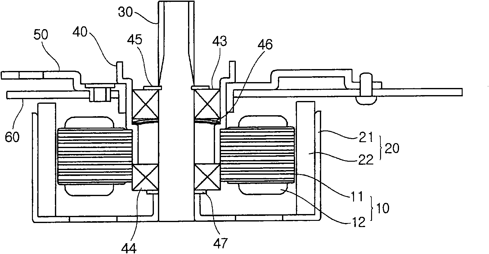
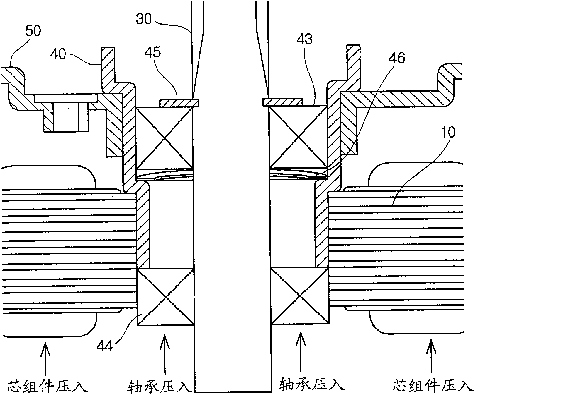
[0032] figure 2 is a sectional view showing the brushless DC motor of the present invention, image 3 yes figure 2 Detailed structural diagram of the core assembly and bearing support structure in .

[0033] Such as figure 2 As shown, the brushless DC motor of the present invention includes: a stator, which is composed of a core assembly 10 formed by winding a coil 12 on a core 11 radially having an inner diameter portion of a certain size inside; and a rotor 20, which It is composed of a ring magnet 22 and a rotor yoke 21. The magnet 22 is opposed to the core assembly 10 at a certain distance (gap portion) from the outer peripheral surface of the core assembly 10. The rotor yoke 21 attaches the magnet 22 to the On the inner peripheral surface, a rotating shaft 30 for rotating the rotor 2...


PUM


Abstract

The invention relates to a structure of supporting core assembly and bearing for a BLDC, especially relates to the following structure of supporting core assembly and bearing for the BLDC, in an outer rotor type BLDC, the core assembly is directly pressed into a bearing box and is fixed to press the bearing (ball bearing or oil-free bearing) into the core assembly to be fixed, thereby reducing the materials, part numbers, manufacturing process and manufacturing costs. The structure is fixed into the core assembly of the stator is characterized in that, an interior diameter part of the core assembly is pressed into a bearing box of the bearing for freely supporting the rotating shaft, and the core assembly can be fixed on the bearing box.

Description

technical field [0001] The present invention relates to a core assembly and a bearing support structure of a brushless DC motor, and more particularly, to a core assembly and a bearing support structure of a brushless DC motor in which the core assembly is directly press-fitted in an outer rotor type brushless DC motor The bearing housing is fixed, and the bearing (ball bearing or oil-free bearing) is directly pressed into the core assembly and fixed, thereby reducing material cost, number of parts and production procedures, thereby reducing manufacturing cost. Background technique [0002] Generally, brushless DC motors include an inner rotor type brushless DC motor and an outer rotor type brushless DC motor. The structure of the outer rotor type brushless DC motor is arranged outside The above-mentioned outer rotor type brushless DC motor includes: a stator composed of a core (hereinafter referred to as "core assembly") formed by winding a coil on a plurality of radial slo...

Claims


Application Information

Patent Timeline
Patent Type & Authority Applications(China)
IPC IPC(8): H02K29/00H02K1/18
CPCH02K5/15H02K5/161H02K7/083H02K15/03H02K21/22
Inventor 李范洪起焕
Owner MOATECH
Why Eureka
Try Eureka