
Hydraulic unit for slip-controlled braking systems

一种液压单元、制动系统的技术,应用在用于弹性流体的泵送装置的部件、制动器、泵元件等方向,能够解决耗费空间的定位、钻孔技术高成本和复杂性等问题,达到降低复杂性和成本的效果

Active Publication Date: 2010-09-08
CONTINENTAL AUTOMOTIVE TECH GMBH
View PDF2 Cites 10 Cited by
  • Summary
  • Abstract
  • Description
  • Claims
  • Application Information

AI Technical Summary

Problems solved by technology

However, this preferential treatment of the receiving opening for the delivery device results in a space-consuming positioning of the remaining components
This embodiment has the disadvantage that all other components with corresponding connecting channels have to be constructed to a certain extent around the receiving opening of the delivery device
This results in a correspondingly high cost and complexity of drilling technology

Method used


Image

  • Hydraulic unit for slip-controlled braking systems
  • Hydraulic unit for slip-controlled braking systems
  • Hydraulic unit for slip-controlled braking systems

Examples


Embodiment Construction

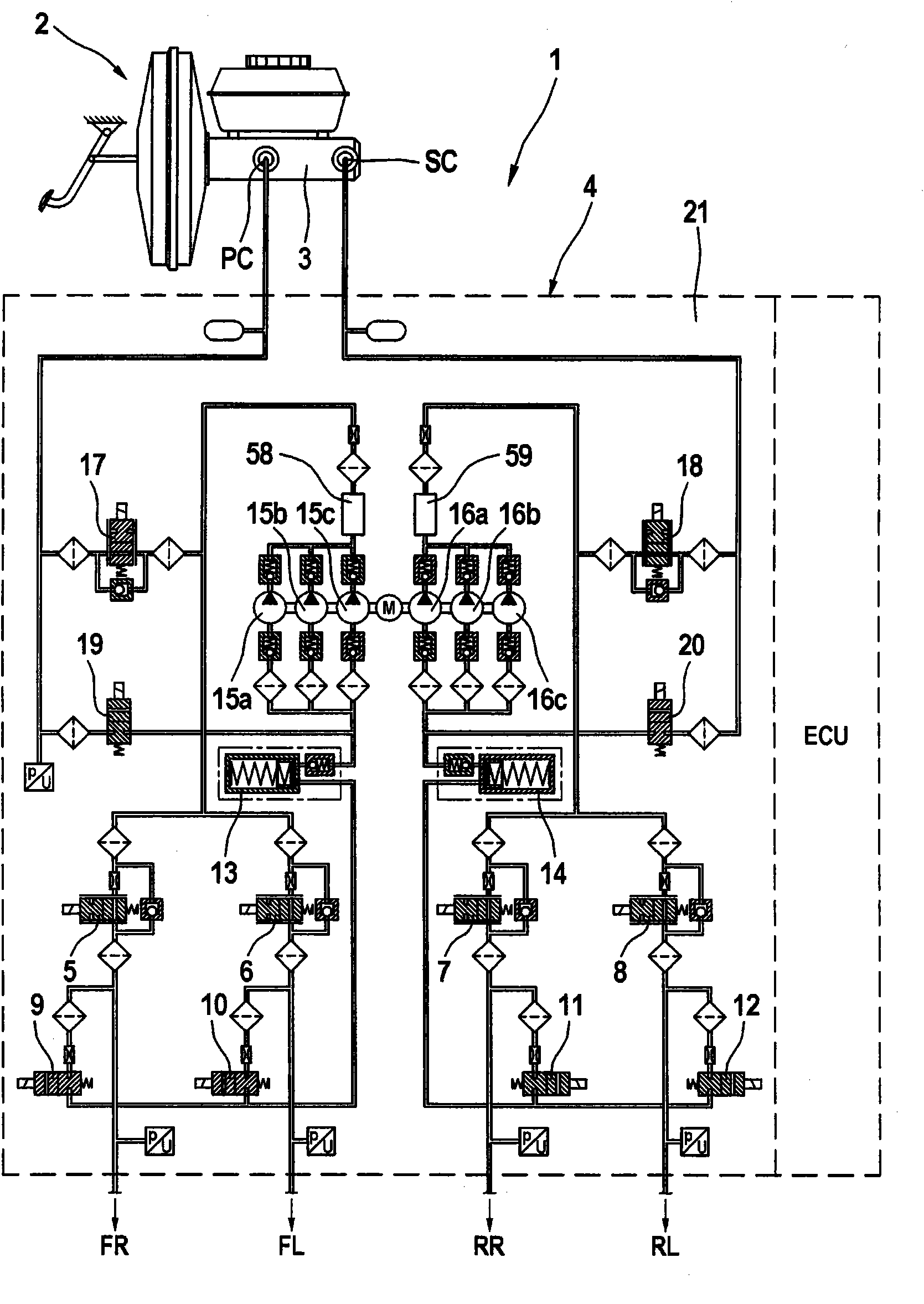
[0025] according to figure 1 , the electrohydraulic braking system 1 comprises an actuating unit 2 with a master cylinder 3 and two wheel brakes FR, FL, RR, RL each arranged in two different hydraulic circuits, the wheel brakes being clustered ground and independently connected to the primary pressure chamber PC or the secondary pressure chamber SC of the master cylinder 3 .

[0026] In the connection between the master cylinder 3 and the wheel brakes FR, FL, RR, RL there is another hydraulic unit 4 with an electronic control unit ECU that can realize braking or driving anti-slip control. For this purpose, the hydraulic unit 4 comprises, in the receiving body 21, inlet valves 5-8, which are open when there is no current, and outlet valves 9-12, which are closed when there is no current, which are connected in pairs to the wheel brakes FR, FL, RR. , upstream of RL.

[0027] By activating the outlet valves 9-12 which are closed when there is no current and discharging the hydr...


PUM


Abstract

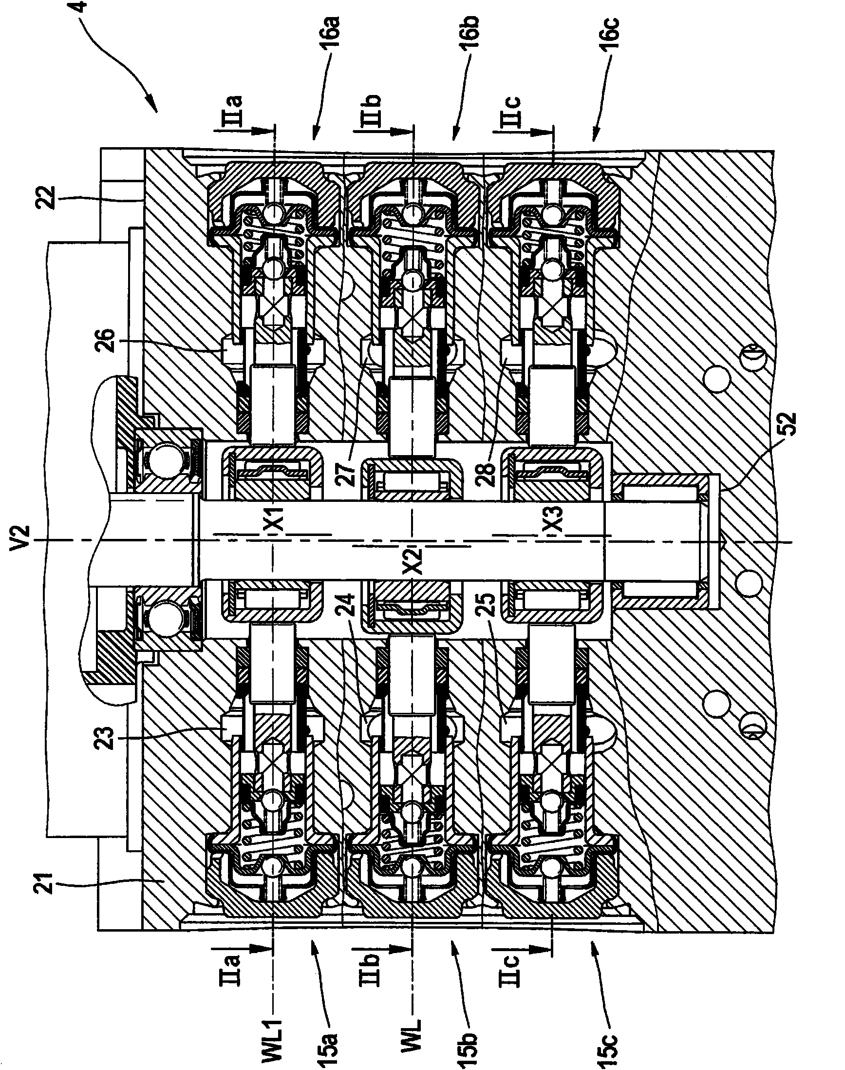
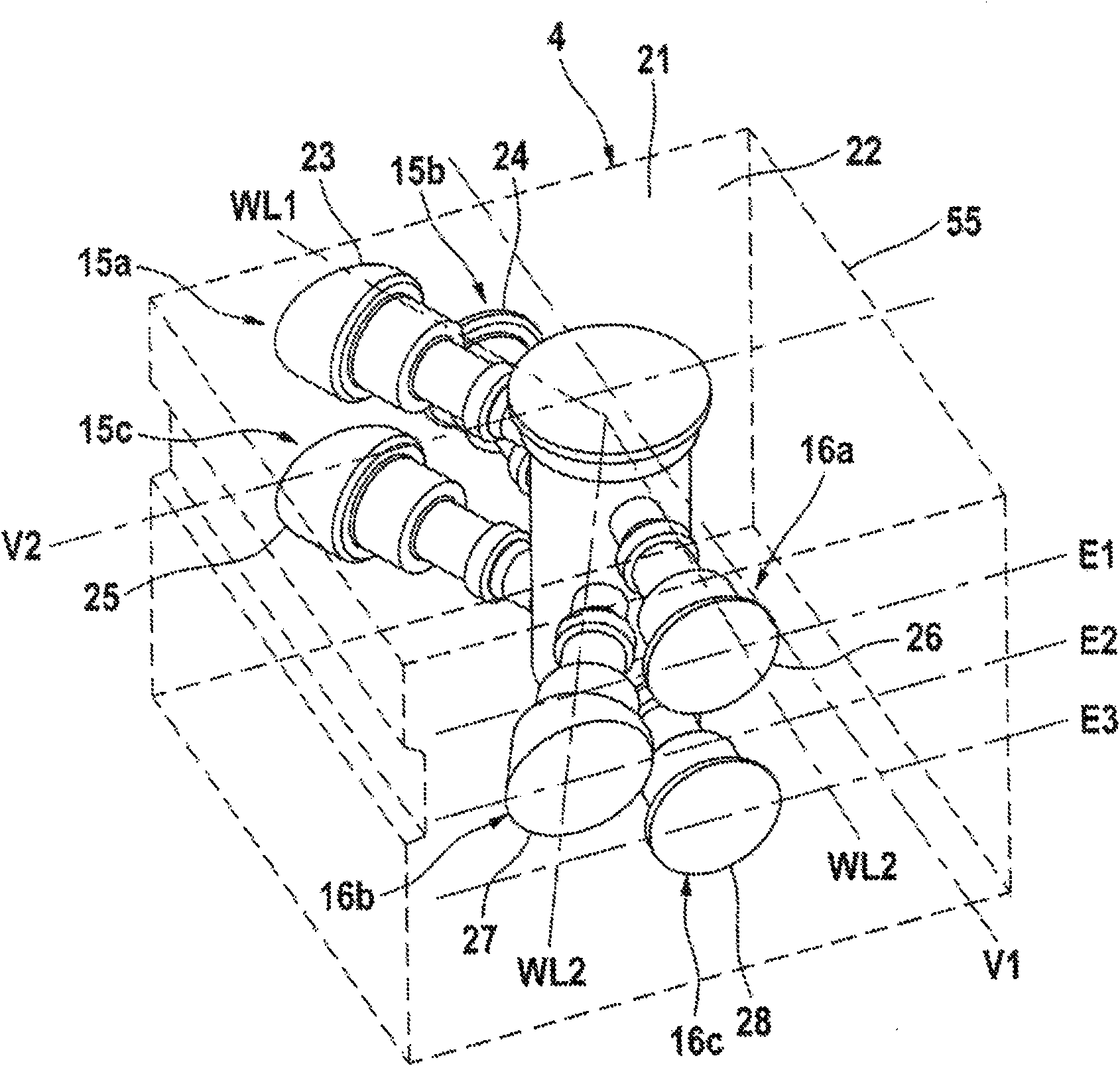
The invention relates to a hydraulic unit for slip-controlled braking systems having a plurality of receiving holes (23-28) for transport devices (15a, 15b, 15c; 16a, 16b, 16c) associated with a plurality of hydraulic circuits bundled into groups, wherein the receiving holes (23-28) are disposed at a distance from each in parallel with the upper side (22), and a drive shaft having eccentrics located at the plane spacing for driving the transport devices (15a, 15b, 15c; 16a, 16b, 16c). In order to provide a compromise optimized for manufacturing a small, convenient hydraulic unit, it is proposed according to the invention that three theoretical planes (E1, E2, E3) are arranged in parallel to the upper side (22), each receiving two V-shaped receiving holes for transport devices (23-28) disposed at an angle to each other, and that the drive shaft comprises three separate eccentrics for driving said transport devices (15a, 15b, 15c; 16a, 16b, 16c).

Description

technical field [0001] The invention relates to a hydraulic unit having the features of the preamble of claim 1 . Background technique [0002] Units of this type are preferably used in electrohydraulic braking systems, in which the driver of the vehicle issues a braking request which is controlled by the braking system to a certain extent on the basis of corresponding actuators, preferably at Executed taking into account the detected environmental conditions. [0003] In electrohydraulic braking systems, pressure is built up in the wheel brakes either directly by means of a pressure source, usually in the form of a positive displacement pump device with pistons, or indirectly based on a pressure accumulator. These mechatronic systems always include complex electronic units with numerous software as well as complex hydraulic units based on hydraulic circuit structures (Schaltplan) and ensure suitable accommodation of the various hydraulic and electrohydraulic components con...

Claims


Application Information

Patent Timeline
Patent Type & Authority Applications(China)
IPC IPC(8): B60T8/36
CPCF04B53/16B60T8/368F04B1/0538F04B53/162B60T8/4031F04B1/0421
Inventor H·加斯托尔A·欣茨P·菲施巴赫-博拉齐奥U·格赖夫
Owner CONTINENTAL AUTOMOTIVE TECH GMBH
Learn More