Workpiece-pressing jig

A fixture and workpiece technology, applied in the field of fixtures, can solve the problems of time-consuming and labor-intensive use, affecting the clamping speed, etc.

Inactive Publication Date: 2010-09-15
宁海县海裕铝业有限公司
View PDF9 Cites 19 Cited by
  • Summary
  • Abstract
  • Description
  • Claims
  • Application Information

AI Technical Summary

Problems solved by technology

At present, the commonly used workpiece clamping method usually uses nuts and bolts for compression and fixation. Although this method is simple, it is time-consuming and laborious to use. At present, there is also a compression fixture that uses cylinder locking. As power to compress the workpiece, a common structure is as follows: a pressure plate is installed and fixed at the end of the cylinder shaft, and the workpiece is installed under the pressure plate when the cylinder is opened. Afte

Method used


Image

  • Workpiece-pressing jig
  • Workpiece-pressing jig

Examples


Embodiment Construction

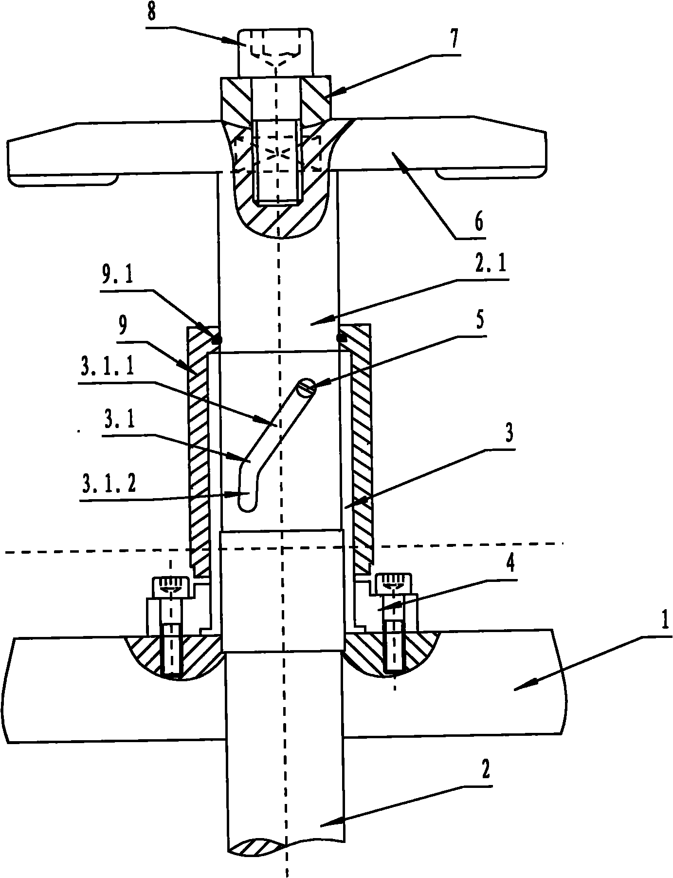
[0013] In order to better illustrate the technical solution of the present invention, the specific implementation manners of the present invention will be described in detail below in conjunction with the accompanying drawings.

[0014] As shown in the drawings, a work piece pressing fixture includes a fixture table 1, a cylinder 2 and a pressure plate 6, and also includes a guide sleeve 3, a fixed seat 4, a guide pin 5 and a locking device for the pressure plate. The guide sleeve 3 is mounted on the cylinder 2 On the cylinder shaft 2.1, the fixed seat 4 fixes the guide sleeve 3 on the fixture table 1, the guide sleeve 3 has a guide groove 3.1, and the guide groove 3.1 has a spiral groove portion 3.1.1 and a straight groove portion 3.1.2, A quarter of the circumference of the cylinder shaft spanned by the helical groove, the guide pin 5 passes through the guide groove 3.1 and is fixed on the cylinder shaft 2.1, the guide sleeve 3 is also provided with a cover 9 outside, and the...


PUM


Abstract

The invention discloses a workpiece-pressing jig. The jig comprises a jig table (1), an air cylinder (2) and a pressure plate (6). The jig is characterized in that the jig also comprises a guide sleeve (3), a fixing seat (4), a guide pin (5) and a pressure plate locking device, wherein the guide sleeve (3) is arranged on the cylinder shaft (2.1) of the air cylinder (2), the fixing seat (4) is used to fix the guide sleeve (3) on the jig table (1); the guide sleeve (3) comprises a guide groove (3.1), the guide groove (3.1) comprises a spiral groove part (3.1.1) and a straight-flute part (3.1.2); the guide pin (5) penetrates through the guide groove (3.1) to be fixed on the cylinder shaft (2.1); and the pressure plate (6) is locked on the end of the cylinder shaft (2.1) by the pressure plate locking device. By using the workpiece-pressing jig, the pressure plate fixed on the cylinder shaft can lean to one side so that the workpiece on the jig table can have larger space in vertical direction, the operation can be convenient and the clamping rate can be greatly improved.

Description

technical field [0001] The invention relates to a fixture, in particular to a workpiece pressing fixture. Background technique [0002] In the machining of parts, it is generally necessary to position and compress the workpiece first. At present, the commonly used workpiece clamping method usually uses nuts and bolts for compression and fixation. Although this method is simple, it is time-consuming and laborious to use. At present, there is also a compression fixture that uses cylinder locking. As power to compress the workpiece, a common structure is as follows: a pressure plate is installed and fixed at the end of the cylinder shaft. When the cylinder is opened, the workpiece is installed under the pressure plate. After positioning, the cylinder retracts to compress the workpiece. Although this structure improves the clamping speed to a certain extent and saves labor compared with the traditional nut and bolt fixing method, when in use, since the workpiece should be place...

Claims


Application Information

Patent Timeline
IPC IPC(8): B25B11/00B23Q3/00
Inventor 张业生葛海明王洪鹏
Owner 宁海县海裕铝业有限公司
Why Eureka
Try Eureka