Pneumatic type chuck

A pneumatic chuck technology, applied in chucks, auxiliary devices, applications, etc., can solve problems such as reduced work efficiency, slow clamping speed, and insufficient clamping force, so as to improve work efficiency, reduce production costs, The effect of high clamping accuracy

Active Publication Date: 2016-01-27
JINAN JINQIANG LASER CNC EQUIP
View PDF6 Cites 9 Cited by
  • Summary
  • Abstract
  • Description
  • Claims
  • Application Information

AI Technical Summary

Problems solved by technology

At present, the manual chucks on the market need to be clamped manually, the clamping speed is slow, the clamping force is not strong enough, the clamping accuracy is low, and

Method used


Image

  • Pneumatic type chuck
  • Pneumatic type chuck
  • Pneumatic type chuck

Examples


Embodiment Construction

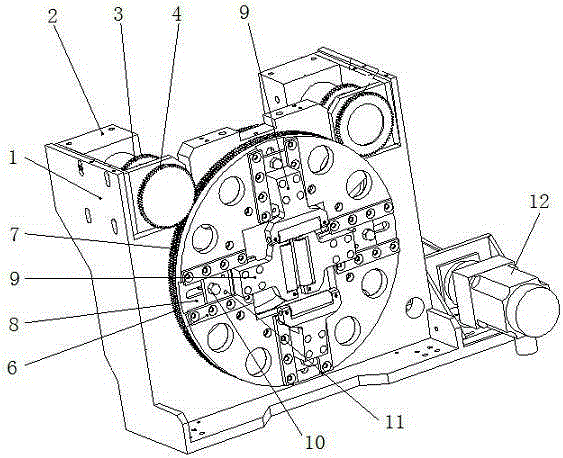
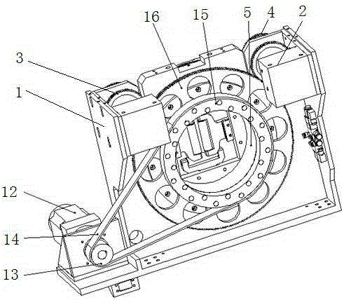
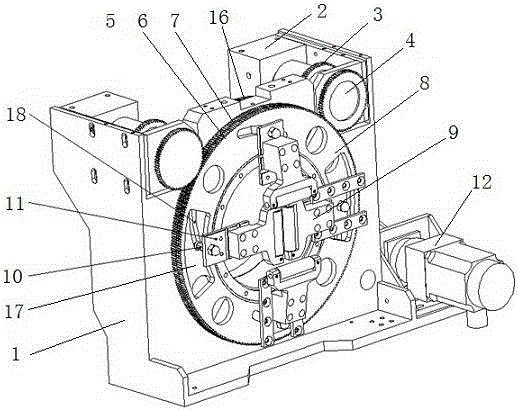
[0014] Accompanying drawing is the specific embodiment of the present invention. Such as Figure 1 to Figure 3 As shown, this kind of pneumatic chuck includes a machine base 1, which is a vertical plate shape, and two air motors 2 arranged left and right are symmetrically arranged on the machine base 1, and each air motor 2 is fixed with a The motor brake disc 3 and the motor locking disc 4, wherein the motor locking disc 4 is located on the front of the base 1, the two motor locking discs 4 are not in the same plane, they are set one after the other, the air motor 2 and the motor brake The moving plate 3 is located on the back of the machine base 1. A round hole is opened in the center of the machine base 1 and a rotating sleeve 5 is installed. The rotating sleeve 5 protrudes from both sides of the machine base 1. 5 is fixed with a brake disc 16 and a driven pulley 15, the brake disc 16 and the driven pulley 15 are driven to rotate by the driving pulley 13 and the synchronou...


PUM


Abstract

The invention relates to the field of laser cutting and particularly discloses a pneumatic type chuck which comprises a machine base. Two pneumatic motors are arranged on the machine base, and each pneumatic motor is provided with a motor braking disk and a motor locking disk; a rotating shaft sleeve is arranged in the center of the machine base, a braking disk and a driven belt wheel are fixedly arranged on the rotating shaft sleeve, and the braking disk are in meshed connection with the two motor braking disks; the rotating shaft sleeve is sleeved by an inner locking disk, an outer locking disk and a rotating disk, the inner locking disk is in meshed connection with one motor locking disk, and the outer locking disk is in meshed connection with the other motor locking disk; and four claws are evenly distributed on the rotating disk, the inner locking disk controls two opposite claws, and the outer locking disk controls the other two claws. According to the pneumatic type chuck, the function diversity is achieved. Furthermore, the pneumatic type chuck is quick in clamping speed, high in clamping accuracy and strong in clamping ability, the producing cost is reduced, and the working efficiency is improved.

Description

(1) Technical field [0001] The invention relates to the field of laser cutting, in particular to a pneumatic chuck. (2) Background technology [0002] At this stage, as the clamping device of the laser pipe cutting machine, the chuck has been widely used due to its good processing quality and high production efficiency. At present, the manual chucks on the market need to be clamped manually, the clamping speed is slow, the clamping force is not strong enough, the clamping accuracy is low, and it is only suitable for clamping and cutting, which increases the cost of human resources and reduces the cost. Work efficiency is not suitable for batch processing enterprises. (3) Contents of the invention [0003] In order to make up for the defects of the prior art, the present invention provides a pneumatic chuck that can automatically clamp workpieces, has rapid clamping, strong clamping force and high clamping precision. [0004] The present invention is achieved through the ...

Claims


Application Information

Patent Timeline
IPC IPC(8): B23K37/04B23K26/38
CPCB23B31/101B23B31/12B23K26/38B23K37/0443B23K2101/06
Inventor 侯秀金
Owner JINAN JINQIANG LASER CNC EQUIP
Why Eureka
Try Eureka