Gas-water separation swirler used in indoor drainage system

A technology of drainage system and cyclone, applied in the field of gas-water separation cyclone, can solve the problems of high price of special pipe fittings, fluctuating pressure of pipe and large floor space, etc. The effect of floor space

Inactive Publication Date: 2010-09-15
HARBIN INST OF TECH
View PDF7 Cites 2 Cited by
  • Summary
  • Abstract
  • Description
  • Claims
  • Application Information

AI Technical Summary

Problems solved by technology

[0006] The purpose of this invention is to solve the problems of large noise, large floor area, easy pressure fluctuation inside the pipeline, damage of water seal and high price of existing special pipe fittings in the indoor drainage system on the market, and proposes an indoor drainage system for indoor drainage system. Air-water separation cyclone in drainage system

Method used


Image

  • Gas-water separation swirler used in indoor drainage system
  • Gas-water separation swirler used in indoor drainage system
  • Gas-water separation swirler used in indoor drainage system

Examples


specific Embodiment approach 1

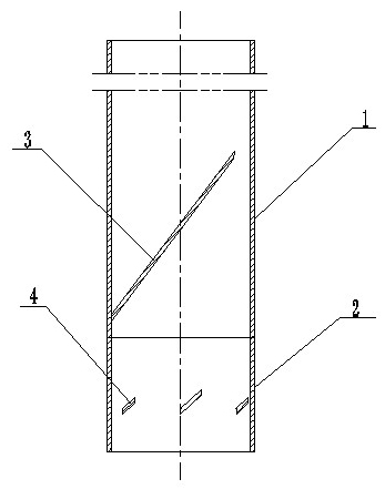
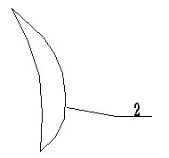
[0010] Specific implementation mode one: combine Figure 1-Figure 8 To illustrate this embodiment, the cyclone of this embodiment is composed of a first pipeline 1, a second pipeline 2, two first guide vanes 3 and a set of second guide vanes 4, each first guide vane The sheet 3 is in the shape of a crescent. Two first flow guide sheets 3 are arranged up and down along the inner wall of the first pipeline 1. The concave surfaces of the two first flow guide sheets 3 are arranged opposite to each other. The inner wall of a pipeline 1 coincides with each other, and the two are fixed, and the angle β between the plane where each first deflector 3 is located and the vertical line is 35° to 45°, and the inner wall of the second pipeline 2 A group of second guide vanes 4 are evenly distributed along the circumference, each second guide vane 4 is triangular in shape, one side of each guide vane 4 is fixedly connected to the inner wall of the second pipeline 2, each second guide vane T...

specific Embodiment approach 2

[0011] Specific implementation mode two: combination Figure 8 To illustrate this embodiment, the three corners of each second deflector 4 in this embodiment are rounded; this structure prevents debris such as hair from being caught in the pipeline. Other components and connections are the same as those in the first embodiment.

specific Embodiment approach 3

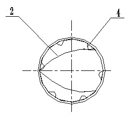
[0012] Specific implementation mode three: combination figure 2 and Figure 8 To describe this embodiment, the number of a set of second guide vanes 4 in this embodiment is 6, and the critical flow rate of the device according to the present invention is large. Other components and connections are the same as those in the first embodiment.


PUM


Abstract

The invention discloses a gas-water separation swirler used in an indoor drainage system, relating to a gas-water separation swirler and aiming to solve the problems of great noise, large floor area, easy pressure oscillation inside the pipeline, water seal damage and expensive traditional special pipe units in the indoor drainage system in the current market. In the gas-water separation swirler, each first flow deflector is of a crescent moon shape, two first flow deflectors are arranged vertically along the inner wall of a first pipeline, concave surfaces of the two first flow deflectors are arranged oppositely, the convex surface of each first flow deflector coincides with the inner wall of the first pipeline in a fixed connection way, a set of second flow deflectors are uniformly distributed along the circumference of the inner wall of a second pipeline, each second flow deflector is in a triangular shape, one side of the each second flow deflector is fixedly connected with the inner wall of the second pipeline, and one end of the first pipeline is connected with one end of the second pipeline into a whole. The invention is applied to the indoor drainage system.

Description

technical field [0001] The invention relates to a gas-water separation cyclone. Background technique [0002] At present, most buildings of indoor drainage adopt traditional indoor drainage system: that is, it consists of drainage pipes and special ventilation risers (special ventilation risers refer to vertical ventilation pipes that are only connected to the main drainage pipe and set up for air circulation in the main drainage pipe). Dual-pipe (or triple-pipe) drainage system. [0003] Although the traditional indoor drainage technology has been applied in our country for decades, some problems are still unresolved, such as noise, waste water overflow, dripping and leakage, etc., and with the development of the times, some new problems It also stands out, such as restrictions on the placement of sanitary ware. Therefore, the improvement and optimization of the traditional indoor drainage system is increasingly showing urgency and importance, and it is very necessary to ...

Claims


Application Information

Patent Timeline
Patent Type & Authority Applications(China)
IPC IPC(8): E03C1/12E03F3/04
Inventor 李欣潘超黄少文杨延栋杨煜祥
Owner HARBIN INST OF TECH
Why Eureka
Try Eureka