Connector for a card

A card connector and card insertion technology, applied in the direction of connection and connection device parts, instruments, etc., can solve the problems of high manufacturing cost, inability to install the card, and inability to unlock the lock, etc., to prevent wrong insertion, reliable The effect of installation

Inactive Publication Date: 2010-09-15
ALPS ALPINE CO LTD
View PDF4 Cites 4 Cited by
  • Summary
  • Abstract
  • Description
  • Claims
  • Application Information

AI Technical Summary

Problems solved by technology

[0006] However, in the conventional card connector as described above, since the free end of the cantilever spring is lifted by utilizing the thickness of the card to release the lock of the sliding member, when the thickness of the card is uneven, the lifting amount of the cantilever spring change, the sliding member may not be sufficiently locked
For example, in the case of a card that is too thin, even though the card is inserted correctly, the lift of the cantilever spring is insufficient and the lock cannot be released, and the card cannot be installed.
In order to solve this problem, it is conceivable to reduce the dimensional tolerance in the thickness direction of the card, but there is a problem that the manufacturing cost becomes high.

Method used


Image

  • Connector for a card
  • Connector for a card
  • Connector for a card

Examples


Embodiment Construction

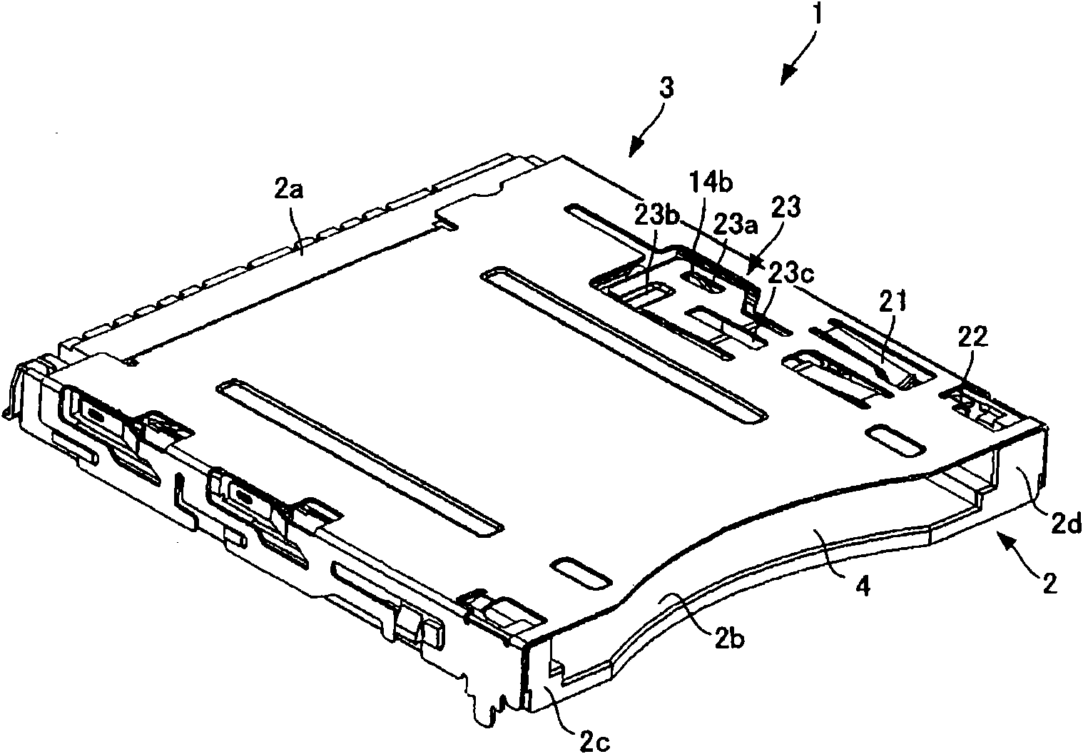
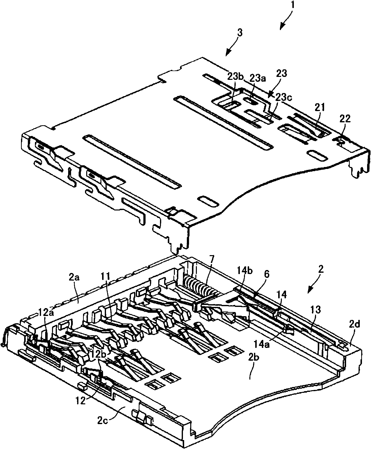
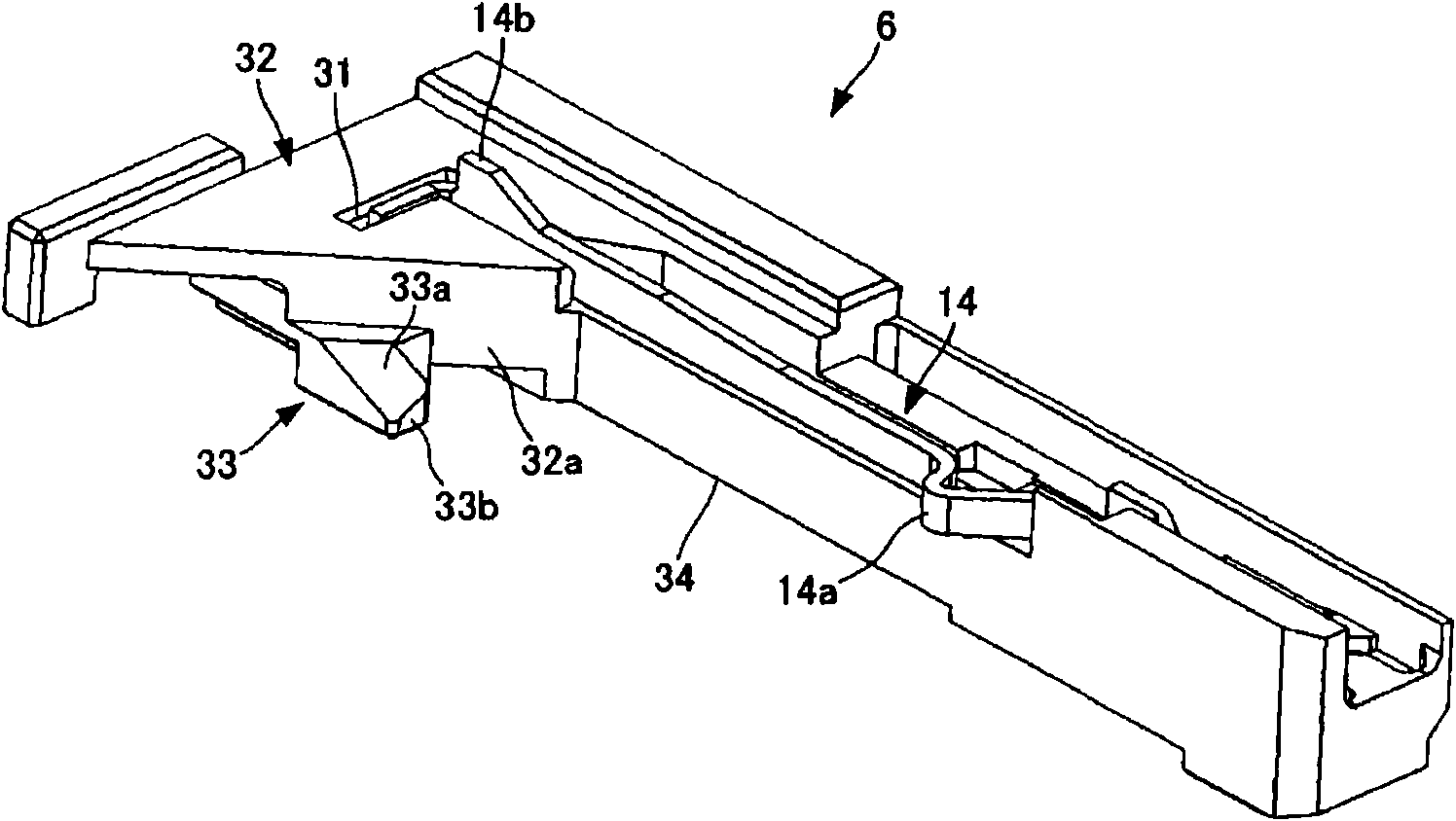
[0053] Hereinafter, embodiments of the present invention will be described in detail with reference to the drawings. In addition, in the following description, the case where this invention is applied to the combination type card connector which can insert two types of cards, a thin card and a thick card, is demonstrated. However, the applicable object of the card connector of this embodiment is not limited to this, and can be changed suitably.

[0054] First, before describing the card connector according to the embodiment of the present invention, a thin card and a thick card to be mounted will be described. Figure 9 It is a plan view of the thin card which concerns on embodiment of this invention, (a) shows a top view, (b) shows a side view. Figure 10In plan views of the thick card according to the embodiment of the present invention, (a) shows a plan view, and (b) shows a side view.

[0055] Such as Figure 9 As shown in (a) and (b), the thin card 41 is a so-called mu...


PUM


Abstract

The invention provides a connector for a card capable of reliably mounting a card when accurately inserting the card and preventing error insertion of the card even though the thickness of the card is not uniform. The connection for the card comprises: a slide component (6) sliding in the connector together with a thin card (41) along the insertion direction of the thin card (41); a locking unit (23) engaged with the slide component (6) along the thickness direction of the connector and for slide-locking the slide component (6) relative to the connector; an insertion position limit unit (32) for separating the locking unit (23) from the slide component (6) by inserting the thin card (41) when accurately inserting the thin card (41), so as to allow the insertion of the thin card (41) to cancel the locking cancel position and preventing the thin card (41) being inserted to the cancel position when wrongly inserting the thin card (41); an increasing unit (33) for increasing the position of the thin card along the thickness direction at the cancel position towards the locking unit (23).

Description

technical field [0001] The present invention relates to a card connector, in particular to a card connector with a structure for preventing wrong insertion of a card. Background technique [0002] In the past, as a card connector with a card wrong insertion prevention structure, when the card is inserted upside down, a card connector that locks a slide member that slides with the card in the card insertion and ejection directions (for example, refer to Patent Document 1). The card connector has a housing into which a card is inserted, and a cantilever spring that locks the sliding of a sliding member is formed on the housing. The cantilever spring is obliquely cut out in the housing and engages with the engaging protrusion of the sliding member on the engaged portion formed on the free end side, thereby locking the sliding of the sliding member. [0003] In addition, an insertion position restriction portion is formed on the slide member. When the card is correctly inserte...

Claims


Application Information

Patent Timeline
Patent Type & Authority Applications(China)
IPC IPC(8): H01R12/16H01R13/645H01R27/00G06K17/00H01R12/00H01R12/72H01R13/639
Inventor 西冈彻
Owner ALPS ALPINE CO LTD
Why Eureka
Try Eureka