
Side-view luminous device

A light-emitting device and side-view technology, which is applied in the direction of lighting devices, lighting device components, light sources, etc., can solve the problem that the light beam cannot be effectively concentrated

Inactive Publication Date: 2010-09-22
EVERLIGHT ELECTRONICS
View PDF2 Cites 0 Cited by
  • Summary
  • Abstract
  • Description
  • Claims
  • Application Information

AI Technical Summary

Problems solved by technology

[0006] Therefore, an object of the present invention is to provide a side-view light emitting device to improve the shortcoming that the light beam emitted by the traditional side-view light emitting device cannot be effectively concentrated.

Method used


Image

  • Side-view luminous device
  • Side-view luminous device
  • Side-view luminous device

Examples


Embodiment Construction

[0036] The side-view light-emitting device of the embodiment of the present invention includes a light-emitting component, a first light-transmitting layer, and a plurality of second light-transmitting layers. The light is guided to the side through the first light-transmitting layer, and the light is concentrated by the second light-transmitting layer, so as to improve the luminous effect of the side-view light emitting device.

[0037] The first transparent layer includes an upper surface and one side surface, and the second transparent layer is disposed on the corresponding side surface of the first transparent layer. Part of the light emitted by the light-emitting component directly passes through the side surface, while part of the light emitted by the light-emitting component can be reflected by the upper surface and pass through the side surface, and the light passing through the side surface can be collected by each second light-transmitting layer and emitted. Accordin...


PUM


Abstract

The invention provides a side-view luminous device which comprises a luminous component, a first light-transmitting layer and a plurality of second light-transmitting layers. The first light-transmitting layer is provided with an upper surface and a lateral surface extending downwards from the upper surface, the second light-transmitting layers are arranged on the lateral surfaces of the first light-transmitting layer which is coated on the luminous component so that partial rays emitted by the luminous component pass through the lateral surfaces and collected by the corresponding second light-transmitting layers and then emit out.

Description

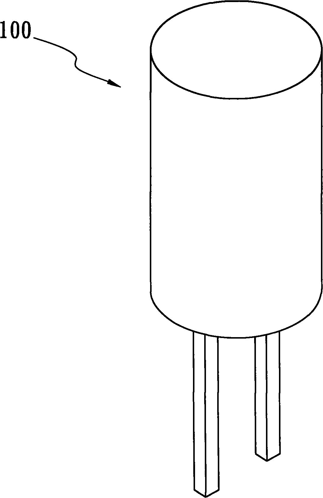
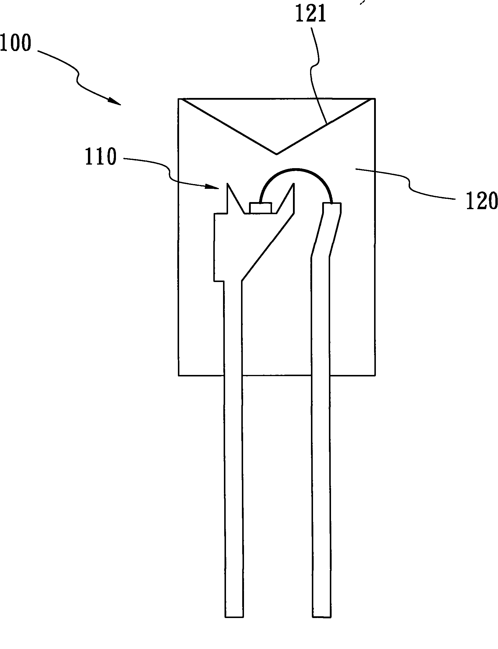
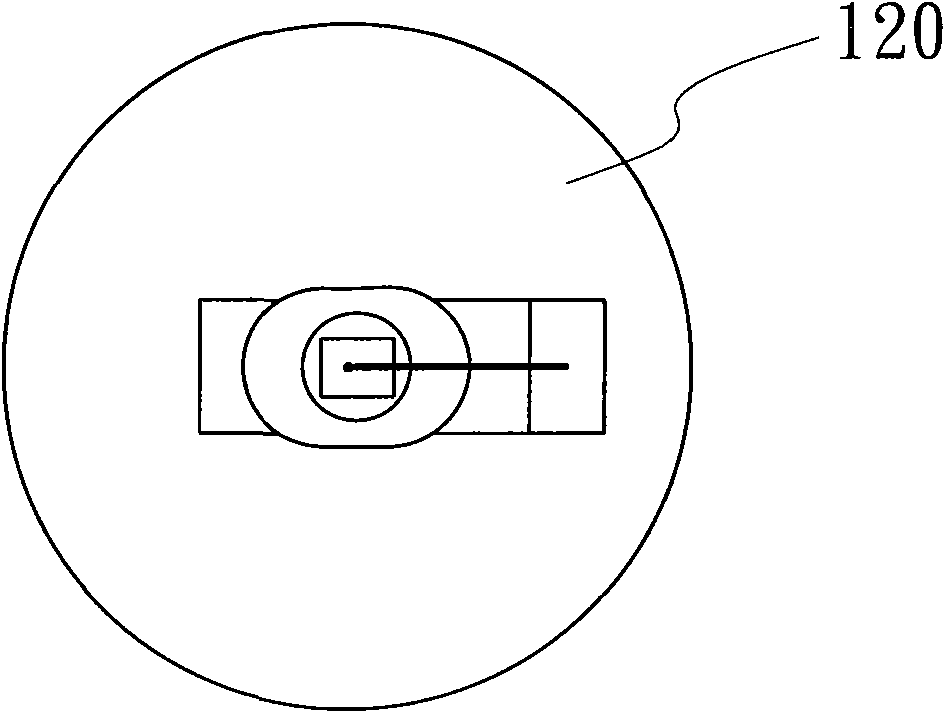
technical field [0001] The present invention relates to a side-view light-emitting device, and in particular to a side-view light-emitting device with a second transparent layer. Background technique [0002] The exterior design of the traditional side-view light-emitting device is that the center point of the mold is concave. When the chip emits light, the light beam can be refracted to the side to reduce the brightness of the center point and increase the luminous intensity of the side. [0003] Figure 1A ~ 1C It is the structure of a traditional side-view light emitting device. Figure 1A is a perspective view of a side-view light emitting device; Figure 1B for Figure 1A A cross-sectional view of a side-view light-emitting device shown, Figure 1C for Figure 1A A top view of the side-view light-emitting device shown. refer to Figure 1A , the side-view light-emitting device 100 may have a cylindrical mold covering the light-emitting component. Refer again Fig...

Claims


Application Information

Patent Timeline
Patent Type & Authority Applications(China)
IPC IPC(8): F21S2/00F21V5/00H01L33/00F21Y101/02
Inventor 马琼玉许嘉芸
Owner EVERLIGHT ELECTRONICS
Learn More