
Frame beam column fire-resistant node with catenary effect and construction method thereof

A catenary and effect technology, which is applied in the direction of fire protection, building material processing, building components, etc., can solve the problem of damage to the collapse resistance of structures, and achieve the effects of reducing residual deformation, relieving thermal expansion stress, and low cost

Inactive Publication Date: 2010-09-29
BEIJING UNIV OF TECH
View PDF0 Cites 35 Cited by
  • Summary
  • Abstract
  • Description
  • Claims
  • Application Information

AI Technical Summary

Problems solved by technology

However, the current domestic and foreign codes ensure the safety of the overall structure by ensuring the stability of individual components under fire. Since the stress state and constraint conditions of individual components are very different from those in the actual structure, the fire response of individual components It cannot represent the response of the overall structure. Some fire resistance tests of the overall structure and actual collapsed structures show that the inner steel beams in the overall structure will show a certain catenary effect in severe fires, which will change the mechanical mechanism of the structure and improve The fire-resistant performance of the structure is improved, and at the same time, the steel columns of the steel columns and steel beam flanges at the joints have local buckling, which is detrimental to the collapse resistance of the structure.

Method used


Image

  • Frame beam column fire-resistant node with catenary effect and construction method thereof
  • Frame beam column fire-resistant node with catenary effect and construction method thereof
  • Frame beam column fire-resistant node with catenary effect and construction method thereof

Examples


Embodiment Construction

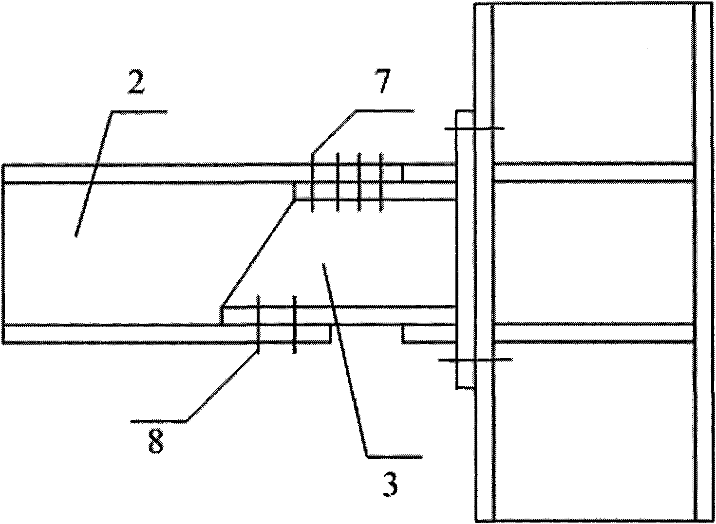
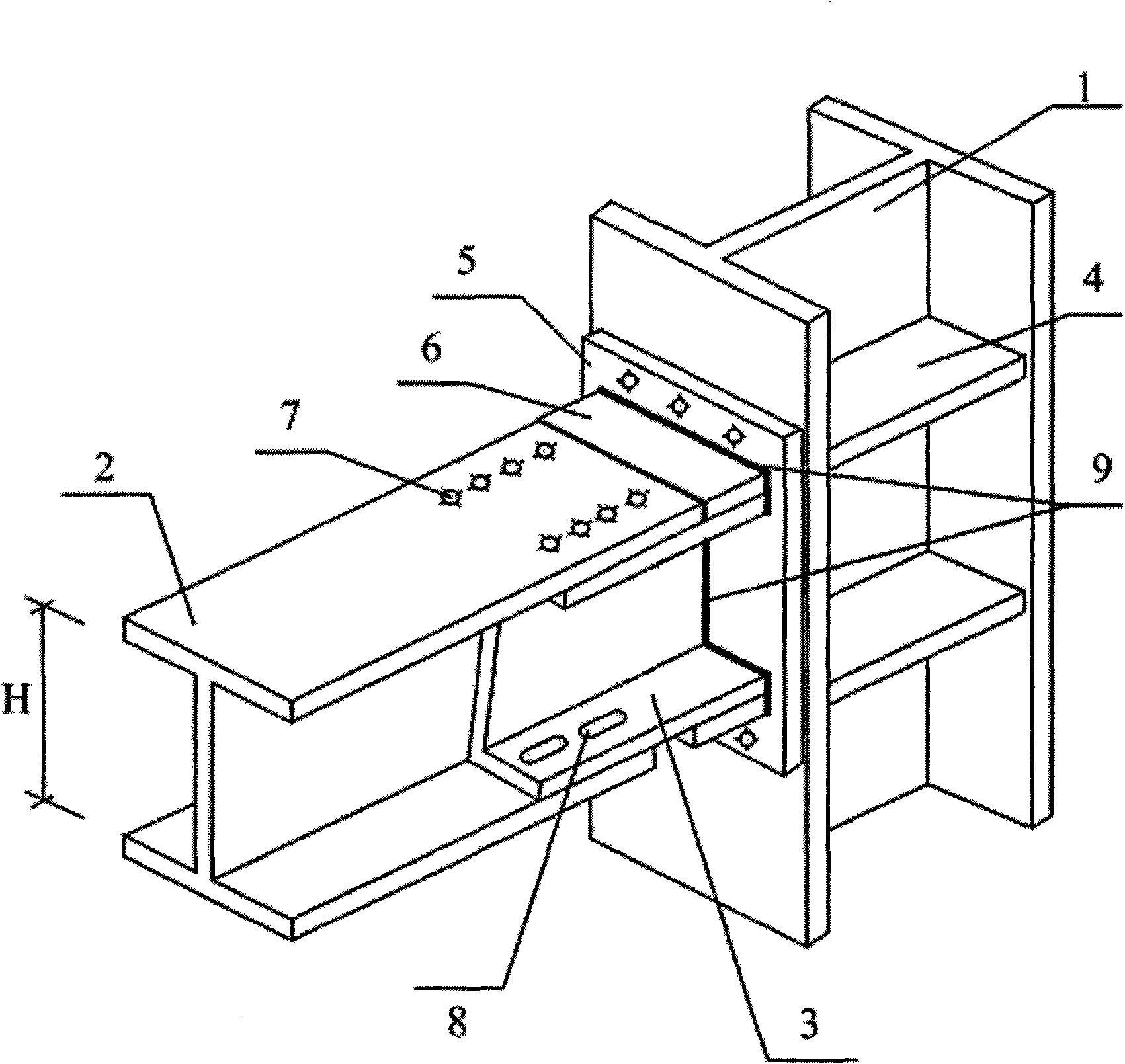
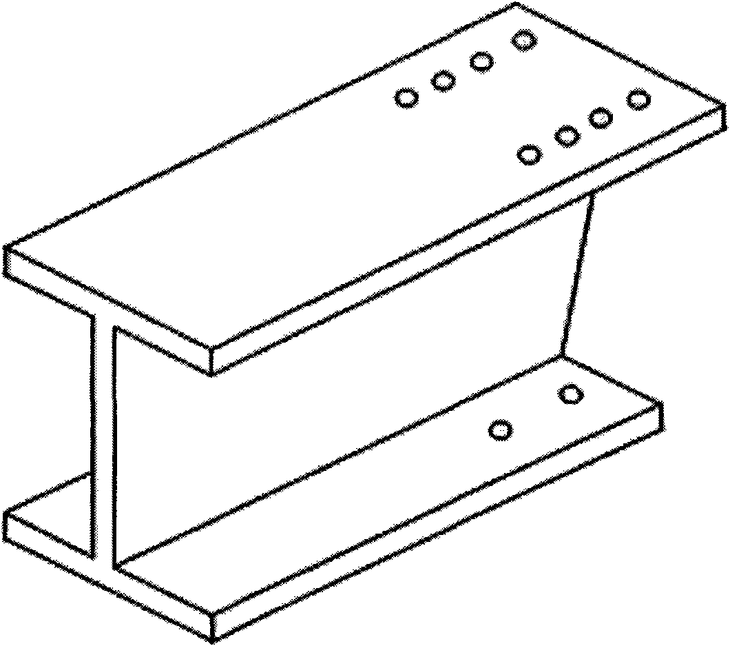
[0031] Examples see Figure 1 to Figure 6 Shown: a frame beam-column fire-resistant joint with catenary effect, including column 1, steel beam 2 and end plate 5, end plate 5 is connected to the side of column 1 by bolts, and steel beam 2 is connected to the side of end plate 5 , the steel beam 2 is I-beam or H-shaped steel, the end of the steel beam 2 has a triangular incision, the cut part is the lower flange and the web, and the cut length of the lower flange is 40% of the overall height H of the steel beam. % to 70%; the notch of the beam is connected with a trapezoidal connecting key 3, the trapezoidal connecting key 3 is composed of double channel steel opposite to the web, its longitudinal section is a positive trapezoid, and the overall height of the trapezoidal connecting key 3 is the same as that of the steel beam 2 The height of the web plate of the trapezoidal connecting key 3 is the same, the upper length L of the trapezoidal connecting key 3 is 1 to 1.5 times the ...


PUM


Abstract

The invention relates to a frame beam column fire-resistant node which is formed by increasing a trapezoidal connecting key at the end part of a steel beam, carrying out high-strength bolt anchoring on an upper flange at the beam end and simultaneously carrying out limited anchoring on a lower flange at the beam end, wherein the lower flange at the beam end has the limited telescopic capacity under the environment of a fire disaster. The implementation of the frame beam column fire-resistant node is as follows: cutting the steel beam with the flanges and a web plate and the trapezoidal connecting key, and then respectively assembling a column, the steel beam, the trapezoidal connecting key, a stiffening plate, an end plate and a steel plate through high-strength bolts, ordinary bolts and welding seams. The frame beam column fire-resistant node is applicable to the industry with higher requirements on the fire-resistant performance and the anti-collapse capacity of the structure and a civil steel frame structure. The frame beam column fire-resistant node has the advantages of simple structure, convenient construction and low cost of required materials, and can avoid the local buckling of the beam under the high-temperature environment, form the catenary effect and have the good fire-resistant performance and the anti-collapse capacity.

Description

(1) Technical field [0001] The invention relates to a structural member, in particular to a frame beam-column fire-resistant node. (2) Background technology [0002] With the development of the economy, frequent building fires will damage or collapse the structure. The purpose of structural fire protection and fire resistance design is to prevent the structure from collapsing within a certain period of time after the fire occurs, so as to ensure the safe evacuation of people in the building. and firefighters have sufficient time to extinguish the fire. However, the current domestic and foreign codes ensure the safety of the overall structure by ensuring the stability of individual components under fire. Since the stress state and constraint conditions of individual components are very different from those in the actual structure, the fire response of individual components It cannot represent the response of the overall structure. Some fire resistance tests of the overall st...

Claims


Application Information

Patent Timeline
IPC IPC(8): E04B1/58E04B1/94E04G21/14
Inventor 陈适才闫维明李振宝何浩祥
Owner BEIJING UNIV OF TECH
Learn More