An "l" type partially prefabricated composite beam and its construction method and application

A technology of composite beams and prefabricated slabs, which is applied to long-strip structural components used for load-bearing, buildings, building components, etc., can solve the problems of not paying enough attention to the connection between beams and floors, only paying attention to the main performance of beam structures, and personal safety threats , to achieve the effect of ensuring normal use and carrying capacity, improving the restraint effect, and enhancing the restraint effect

Active Publication Date: 2020-02-18
JIANGNAN UNIV
View PDF5 Cites 0 Cited by
  • Summary
  • Abstract
  • Description
  • Claims
  • Application Information

AI Technical Summary

Problems solved by technology

[0007] In addition, since the existing beam structure design is based on the seismic concept of "strong column weak beam, strong shear weak bending, strong joint weak member", almost all steel-concrete composite beams and some prefabricated composite beams The beam structure only pays attention to the performance of the main body of the beam structure, and does not pay enough attention to the connection between the beam and the floor. This leads to the phenomenon that the main structure of the beam does not collapse but the floor falls off under the earthquake, which poses a great threat to personal safety.

Method used


Image

  • An "l" type partially prefabricated composite beam and its construction method and application
  • An "l" type partially prefabricated composite beam and its construction method and application
  • An "l" type partially prefabricated composite beam and its construction method and application

Examples


Embodiment 1

[0065] Example 1: An "L"-shaped partially prefabricated composite beam

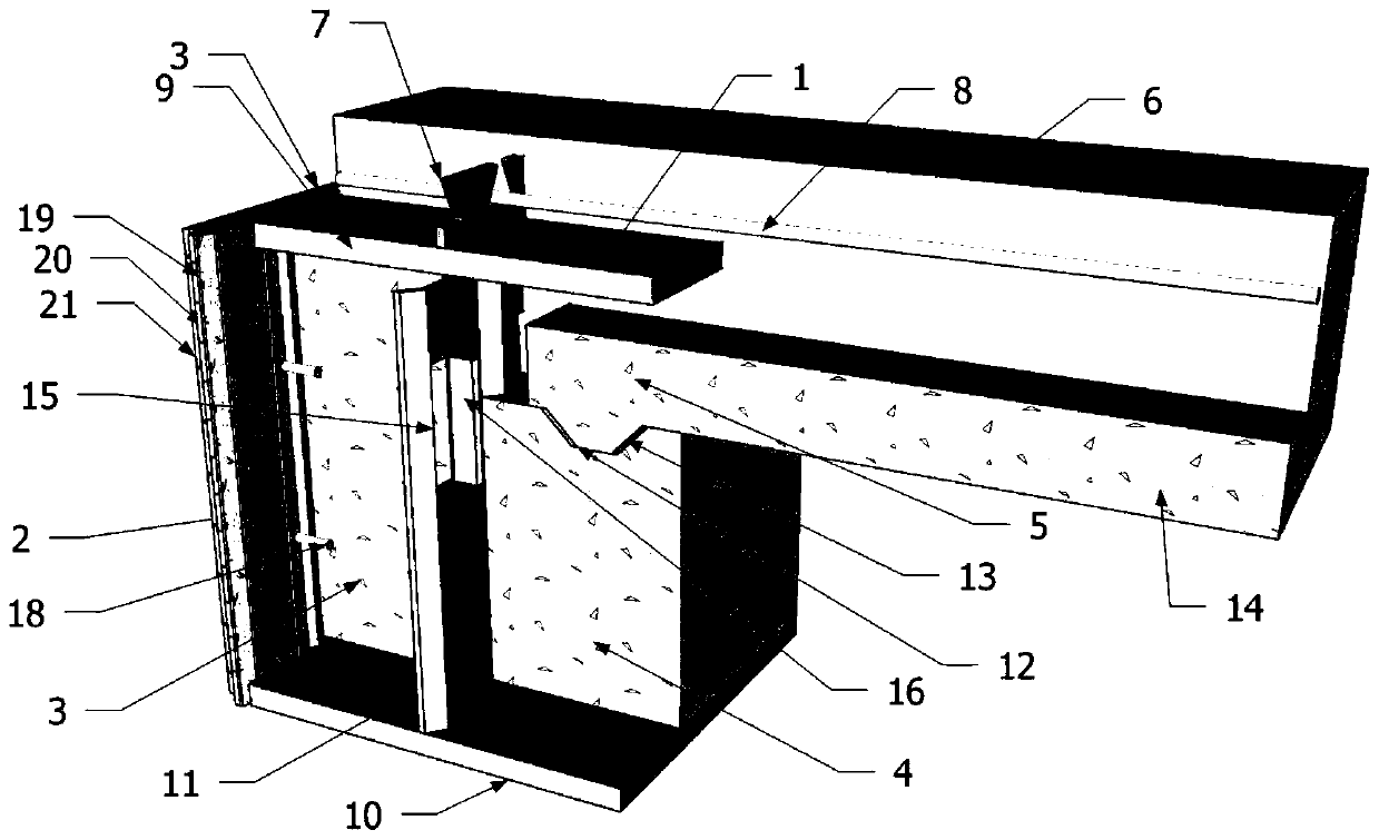
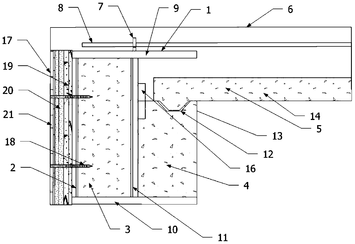
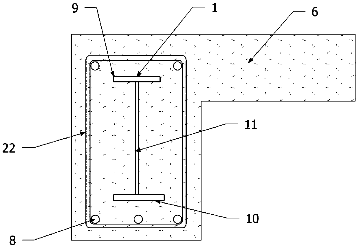
[0066] Such as Figure 1-2 , an "L"-shaped partially prefabricated composite beam includes H-shaped steel 1, panel 2, first precast concrete 3, second precast concrete 4, precast concrete floor slab 5, cast-in-place concrete 6, connector 7 and longitudinal reinforcement 8;

[0067] The H-shaped steel 1 includes an upper flange plate 9, a lower flange plate 10 and a web 11;

[0068] The trim plate 2 is located on one side of the H-shaped steel 1 and the two ends of the trim plate 2 are respectively connected to the upper flange plate 9 and the lower flange plate 10 of the H-shaped steel 1;

[0069] The first precast concrete 3 is filled in the cavity formed by the upper flange plate 9, the lower flange plate 10, the web plate 11 and the trim plate 2 of the H-shaped steel 1;

[0070] The second prefabricated concrete 4 is located on the other side of the H-shaped steel 1 that is not connected to the panel...

Embodiment 2

[0094] Example 2: A construction method for "L"-shaped partially prefabricated composite beams

[0095] Specific steps are as follows:

[0096] (1) According to the design, three-sided punching is carried out on the web 11 of the H-shaped steel 1, and the punched part is bent to obtain the H-shaped steel 1 provided with the opening 15 and the shear key 16; It is welded between the upper flange plate 9 and the lower flange plate 10 of the H-shaped steel 1, and the connecting piece 7 is welded above the upper flange plate 9 to obtain the steel frame; the prefabricated plate 17 is fixed to the trim plate by bolts 18 2, the first precast concrete 3 is poured in the cavity formed by the upper flange plate 9, the lower flange plate 10, the web 11 and the trim plate 2 of the H-shaped steel 1, and the second precast concrete 4 is poured in the H-shaped steel Between the upper flange plate 9 and the lower flange plate 10 of 1, a prefabricated part A is obtained;

[0097] (2) Accordin...

Embodiment 3

[0099] Example 3: Detection of an "L"-shaped partially prefabricated composite beam

[0100] Specific steps are as follows:

[0101] A "L" type partial prefabricated composite beam:

[0102] The size of the upper flange plate is 200mm×6mm; the size of the lower flange plate is 200mm×8mm; the height of the web plate is 416mm and the thickness is 4mm; the size of the side plate is 416mm×3mm and the specification is W94×20×2; the opening The size of the shear key is 200mm×20mm, the distance between the symmetry axis parallel to the longitudinal direction of the beam and the lower flange plate is 292mm; the size of the single-row hole steel plate shear connector is 25mm×4mm, and the hole is trapezoidal , the side lengths of the upper bottom and the lower bottom are 15mm and 30mm respectively; the steel plates are all made of Q235; the diameter of the longitudinal reinforcement is 8mm, and the steel bar of HRB335 grade is used; the diameter of the self-tapping bolt is 10mm, the le...


PUM


Abstract

The invention discloses an L-shaped partially-prefabricated composite beam, and a construction method and application thereof, and belongs to the technical field of buildings. The composite beam givesfull play to the performance of steel and concrete materials. Concrete is packed in profile steel, the constraint effect on the concrete is enhanced due to the existence of the profile steel, and thepossibility of local buckling or overall instability of the profile steel is reduced due to the existence of the concrete, so that the bearing capacity of the composite beam is improved, and meanwhile, the purpose of reducing the section size of the composite beam is achieved. The web plate of the composite beam is a corrugated plate with higher shear strength, and the constraint effect on concrete is greatly improved due to higher lateral rigidity of the web plate. Aiming at the bonding among second precast concrete, cast-in-place concrete and H-shaped steel, the composite beam adopts a modeof punching a shear key on the web plate of the H-shaped steel, so that the shear key is partially arranged in the second precast concrete, and the shear key is partially arranged in the cast-in-place concrete, thereby ensuring co-working of the concrete and the concrete and co-working of the steel and the concrete.

Description

technical field [0001] The invention relates to an "L"-shaped partially prefabricated composite beam and its construction method and application, belonging to the technical field of construction. Background technique [0002] There are many types of composite structures. In a broad sense, a composite structure refers to a structure in which two or more different materials form a structure or component and work together (Composite Structure). Among them, steel-concrete composite structure is the fifth largest type of structure developed after wood structure, masonry structure, reinforced concrete structure and steel structure. [0003] Steel-concrete composite beam is a kind of steel-concrete composite structure, which refers to the steel-concrete composite beam composed of I-beam or H-shaped steel and concrete filled in the flanges on both sides, which can give full play to the material properties of steel and concrete , which is embodied as follows: the concrete in the fla...

Claims


Application Information

Patent Timeline
Patent Type & Authority Patents(China)
IPC IPC(8): E04C3/293
Inventor 邹昀康金鑫李天祺丁杰钱慧超
Owner JIANGNAN UNIV
Why Eureka
Try Eureka