Check patentability & draft patents in minutes with Patsnap Eureka AI!

Connector having lock mechanism for keeping socket and a header coupled, and method for manufacturing the connector

A locking mechanism and connector technology, applied in fixed connection, two-part connection device, connection, etc., can solve the problems of increased number of steps, complicated structure of head 42, flatness damage of head contact 47, etc. Effect

Inactive Publication Date: 2010-09-29
PANASONIC CORP
View PDF4 Cites 9 Cited by
  • Summary
  • Abstract
  • Description
  • Claims
  • Application Information

AI Technical Summary

Problems solved by technology

Since the head contact 47 is made of an easily bendable material, the flatness of the head contact 47 may be damaged by an inadvertent force applied thereto.
[0008] In addition, the manufacturing process also has the problem of increasing the number of steps involved due to the complicated structure of the head 42 (connector provided with the locking mechanism).

Method used


Image

  • Connector having lock mechanism for keeping socket and a header coupled, and method for manufacturing the connector
  • Connector having lock mechanism for keeping socket and a header coupled, and method for manufacturing the connector
  • Connector having lock mechanism for keeping socket and a header coupled, and method for manufacturing the connector

Examples


Embodiment Construction

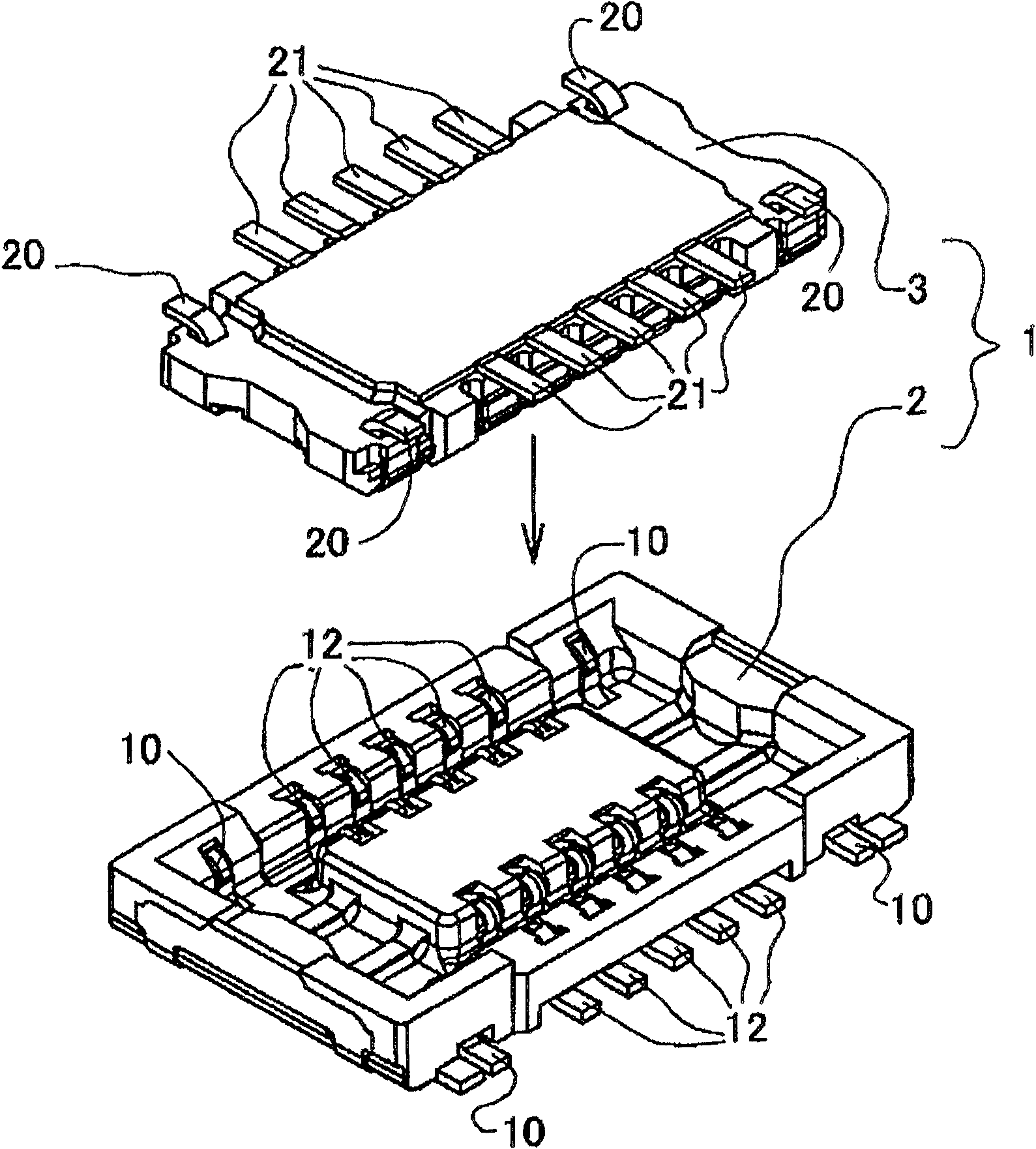
[0030] A connector configuration according to an embodiment of the present invention, which is provided with a locking mechanism for maintaining a receptacle and a head in a combined state, will first be described with reference to the accompanying drawings. It should be understood that the following descriptions do not limit the scope of the present invention, but are intended to increase understanding of the embodiments of the present invention.

[0031] see figure 1 , the connector 1 according to the embodiment of the present invention includes a receptacle 2 and a head 3 . The first thing to introduce is the structure of the socket 2 and the head 3, and then the method of combining them will be introduced.

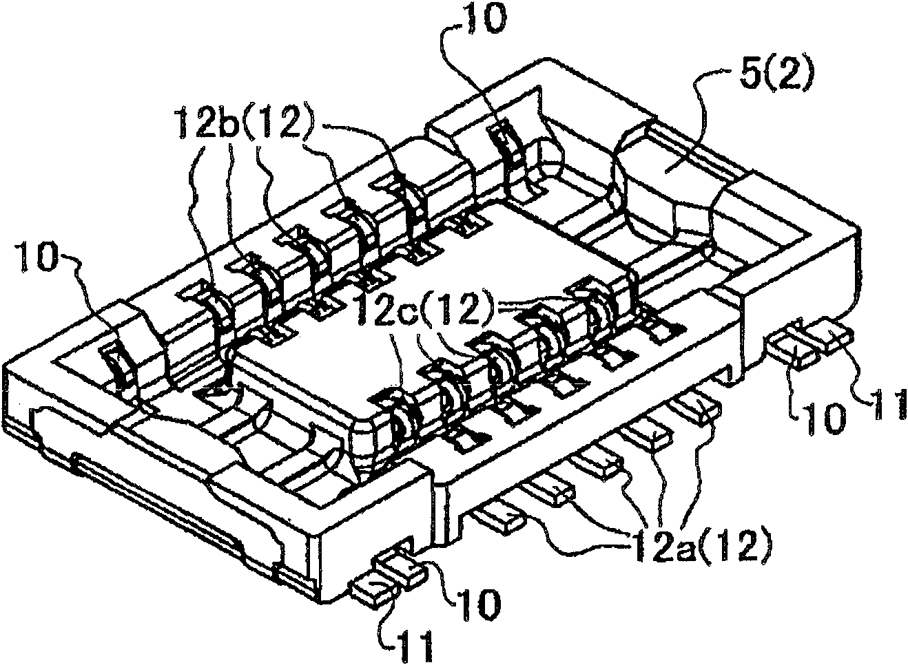
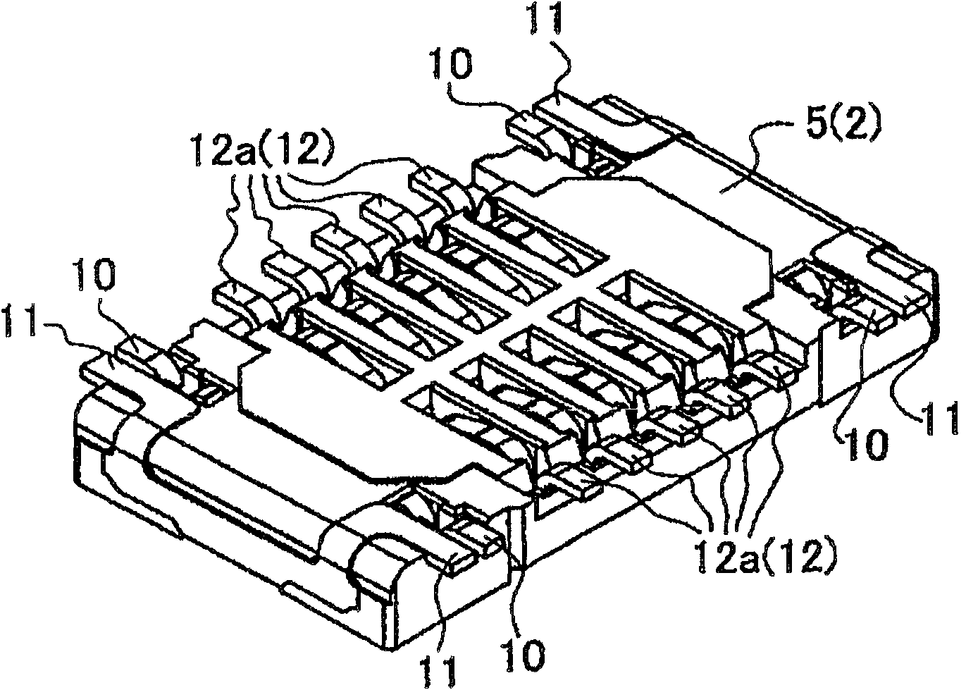
[0032] Outlet 2 will be introduced first. Figure 2A draws the front side of receptacle 2, while Figure 2B Its rear side is drawn. The socket 2 includes a socket main body 5 , a latch (lock mechanism) 10 on the socket side, a retainer portion (retainer mechanism)...


PUM


Abstract

A connector includes a socket having a generally rectangular shape, the socket including socket contacts, lock mechanisms and retainer mechanisms; and a header having a generally rectangular shape, the header including header contacts and lock mechanisms and being couplable with the socket. The lock mechanisms of the socket and the header are respectively formed from the socket contacts and the header contacts, the lock mechanisms of the socket being formed by cutting away a portion of the socket contacts. The lock mechanisms of the header also serve as retainer mechanisms thereof. The lock mechanisms of the socket and the header are arranged substantially in the same row as the socket contacts and the header contacts and positioned near four corners of the socket and the header, respectively. The lock mechanisms of the socket and the header are configured to keep the socket and the header in a coupled state.

Description

technical field [0001] The present invention relates to a connector provided with a locking mechanism for keeping a socket and a head in a combined state, wherein they are combined and electrically connected to each other. Background technique [0002] Portable devices, which are experiencing rapid miniaturization, must reduce the height of connectors and contacts (or signal terminals), which is called profile reduction. However, this reduction in profile comes with a reduction in forces acting on the receptacle and header engagement. For this reason, portable devices are prone to shocks caused by dropping or other factors, and need to have a configuration that makes it difficult to separate the socket and the head. A connector having a locking mechanism that keeps a receptacle and a head in an engaged state is disclosed in Japanese Patent Application Laid-Open No. 2003-234150. [0003] In addition to the connector disclosed in Japanese Patent Application Laid-Open No. 200...

Claims


Application Information

Patent Timeline
Patent Type & Authority Applications(China)
IPC IPC(8): H01R24/00H01R13/639H01R43/00H01R12/00H01R12/65H01R12/71H01R12/78H01R12/79H01R43/24
CPCH01R12/716H01R13/20H01R12/73
Inventor 宫崎洋二大仓健治
Owner PANASONIC CORP
Features
  • R&D
  • Intellectual Property
  • Life Sciences
  • Materials
  • Tech Scout
  • Unparalleled Data Quality
  • Higher Quality Content
  • 60% Fewer Hallucinations
Learn More