Key-closed mechanical lock

A mechanical lock and key technology, applied in the field of locks that change the traditional unlocking method, can solve problems such as lock opening, achieve the effect of reducing weight, preventing violent unlocking, and being easy to trust

Inactive Publication Date: 2010-10-06
刘攻关
View PDF1 Cites 6 Cited by
  • Summary
  • Abstract
  • Description
  • Claims
  • Application Information

AI Technical Summary

Problems solved by technology

And whether the lock can be successfully unlocked often depends on whether the key can be turned. If violent rotation is performed, even if the key does not match, the lock may be opened.

Method used


Image

  • Key-closed mechanical lock
  • Key-closed mechanical lock
  • Key-closed mechanical lock

Examples


Embodiment 1

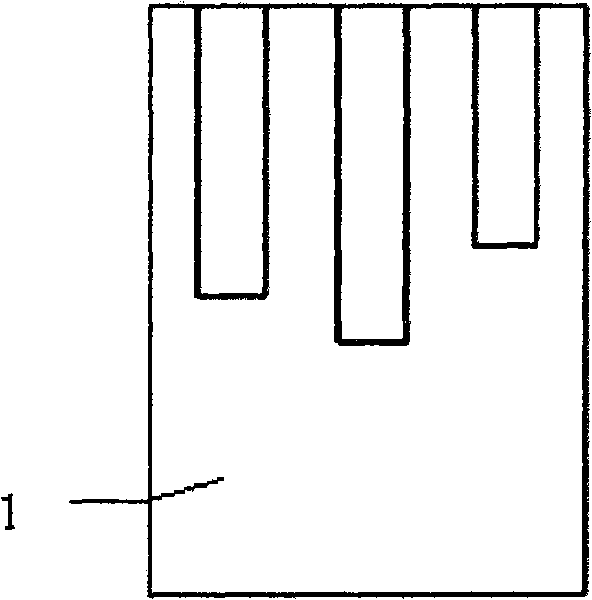
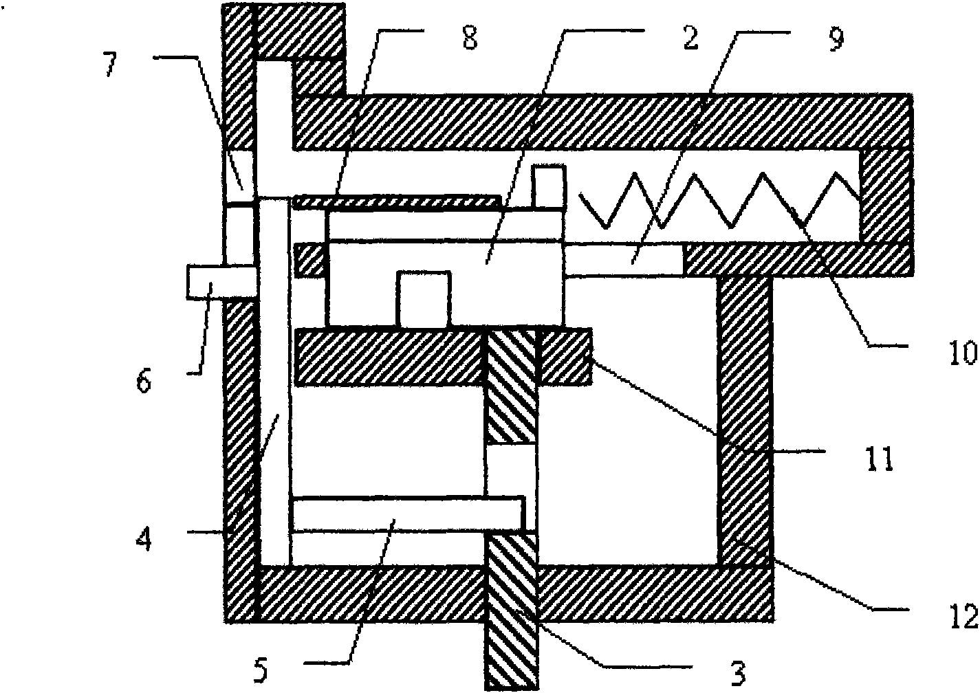
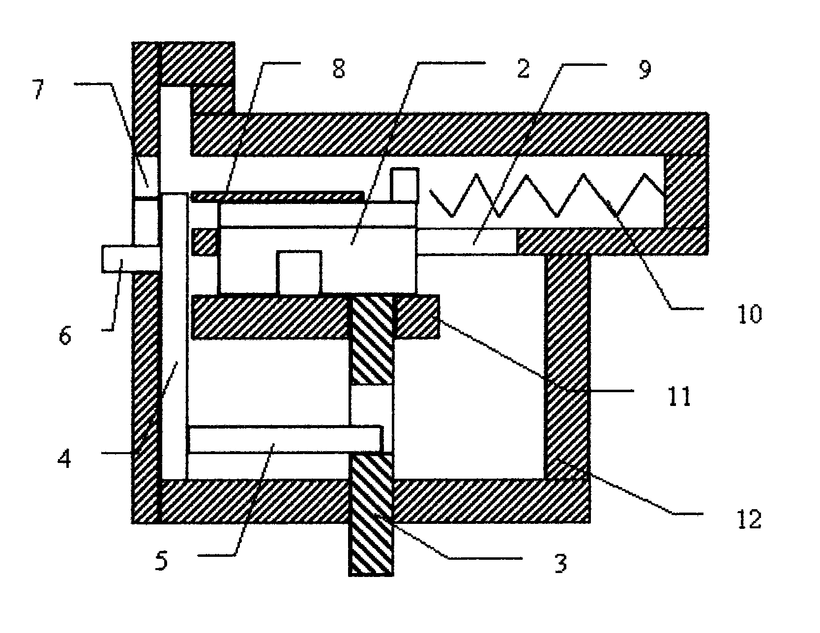
[0034] When the lock is in the locked state and needs to be unlocked, first insert the key (1) along the lock hole (7), only when the width and depth of the groove on the key correspond to the identification element on the lock cylinder, The key can push the lock cylinder to move forward, and only when it fits completely can the state that the key is enclosed in the lock hole can be formed. Then hold the handle (6) and lift it up, then the baffle plate (4) will be lifted along the direction of the lift, just in time to seal the lock hole (7), if you continue to lift the handle (6), the push-pull rod (5) Just push deadbolt (3) in the groove of lock cylinder post (2) bottom surface, then the outer side end of deadbolt (3) is withdrawn, has formed open state.

Embodiment 2

[0036] When the lock is in the open state, when it needs to be closed, at first hold the handle (6) and move downwards, and the dead bolt (3) has just left the groove on the bottom surface of the lock cylinder stem (2), and the dead bolt (3) will move on the other side One end enters the recess in the wall or the door frame, then the spring (10) will bounce back the lock cylinder stem (2) at this time, and the key (1) will be ejected from the lock hole (7) at the same time, and the closed state of the lock will be completed . If the dead bolt (3) does not leave the depression on the bottom surface of the lock cylinder post (2), the key (1) will not be ejected.

Embodiment 3

[0038] If the key (1) is not put in or the key does not match the lock cylinder, directly hold the handle (6) in this state and move upwards, because the lock tongue (3) cannot enter the lock cylinder cylinder (2) In the depression on the bottom surface, the lockset cannot be opened, and the unlocked state cannot be completed. And this moment lockhole (7) has been closed, so can not put into any unlocking tool, carries out technical unlocking. If the unlocking tool is put in first, the lock hole (7) cannot be closed at this time, and the baffle plate (4) cannot be moved up, so that the dead bolt (3) cannot enter the groove on the bottom surface of the lock cylinder (2) Inside, the operation of unlocking cannot be realized.


PUM


Abstract

The invention discloses a key-closed mechanical lock, comprising a lock cylinder, a lock body, a bolt, a push and pull plate and a key. The specialty of the lock depends on the matching correspondence between the stem of the lock cylinder and the slot of the key. A gap containing a pit at the lower bottom surface of the stem of the lock cylinder just correspond to the bolt. The middle of the bolt is connected with a push and pull rod which can move inwards and outwards. When moving inwards, the push and pull rod can enter the pit at the lower bottom of the lock cylinder to form an unlocking state. When moving outwards, the push and pull rod can form the locking state of the lock. The push and pull plate comprises the push and pull rod, a baffle plate and a handle, wherein the handle is used as the strength bearing point for unlocking the lock; the baffle plate can close the key in a key hole in the process of unlocking; and the push and pull rod enables the bolt to move inwards and outwards to perform the functions of unlocking and locking. The invention provides the mechanical lock which can only perform unlocking operation when the key is totally put in the key hole and after the key hole is closed, thereby improving the thievery prevention. The invention changes the traditional unlocking habit, and the cost is reduced simultaneously.

Description

technical field [0001] The invention relates to a keyed mechanical lock, which belongs to a lockset which changes the traditional unlocking method. Background technique [0002] Existing mechanical locks have been widely used in various safes, anti-theft doors, outdoor communication facilities, etc. With the wide application of locks, various unlocking tools or master keys have emerged in an endless stream, but all mechanical locks require hand-held keys to operate. To unlock the lock, put the key into the lock hole and turn the key by hand to turn the lock cylinder to open the lock. Therefore, as long as the lockhole is open, there is a possibility of being opened by a master key or other unlocking tools. No matter what password, permutation and combination, as long as the lockhole is open, it can be tested repeatedly until it is opened. Therefore a kind of lockset goes on the market soon, just has various unlocking tools to come out. Even a combination lock with a sophis...

Claims


Application Information

Patent Timeline
Patent Type & Authority Applications(China)
IPC IPC(8): E05B27/10E05B35/00
Inventor 刘攻关
Owner 刘攻关
Why Eureka
Try Eureka