Adjustable image display and acquisition device

An image display and acquisition device technology, applied in static indicators, cathode ray tube indicators, instruments, etc., can solve the problem that it is difficult for the camera to realize the user's frontal image, and achieve the effect of shooting

Active Publication Date: 2010-10-06
LENOVO (BEIJING) CO LTD
View PDF0 Cites 12 Cited by
  • Summary
  • Abstract
  • Description
  • Claims
  • Application Information

AI Technical Summary

Problems solved by technology

However, since the position of the user and the display is very close, and the size of the display tends to be larger and larger, unless the user keeps focusing on the middle of

Method used


Image

  • Adjustable image display and acquisition device
  • Adjustable image display and acquisition device
  • Adjustable image display and acquisition device

Examples


no. 1 example

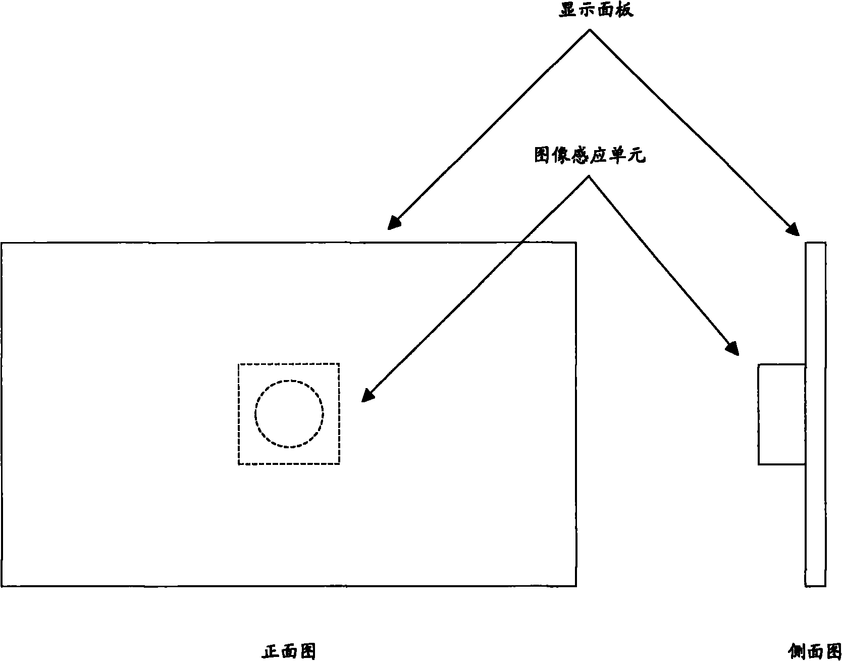
[0027] Figure 5 is a schematic diagram showing that the rear image sensing unit moves with the window according to the first exemplary embodiment of the present invention. Wherein, the image sensing device placed behind the display panel can be moved and positioned on the cross center of the active window on the display panel in real time.

[0028] Specifically, at first, to obtain the position and size coordinates of the current active window, the specific acquisition means can obtain the coordinates and size of the current active window through an interface function (such as an API function) provided by the operating system (such as WINDOWS); secondly, calculate the The coordinates of the center of the cross; then, adjust the camera to the coordinates of the center of the cross.

[0029] Of course, since the camera can be adjusted according to the settings, it is not necessary to adjust the camera to the exact center of the window. And if the window range is large and con...

no. 2 example

[0032] In addition, the image sensing device placed behind the display panel can move and track the operator's visual cone in real time, allowing the image sensing device to perform visual tracking of the operator.

[0033] Specifically, firstly, acquire the user's face image to locate the user's eyes; secondly, calculate the midpoint coordinates of the connecting line of the two eyes; then adjust the image sensing unit to the midpoint coordinates or the area close to the midpoint coordinates on the screen the corresponding area. Regarding the coordinate reference system, a unified coordinate system can be adopted with the operating system, for example, the coordinate origin is set at the upper left corner or the lower left corner of the display screen.

[0034] Specifically, other methods can be used for visual tracking. First, the corresponding relationship between the binocular image and the gaze screen coordinates is pre-stored. When the user’s face image is obtained, the ...

no. 3 example

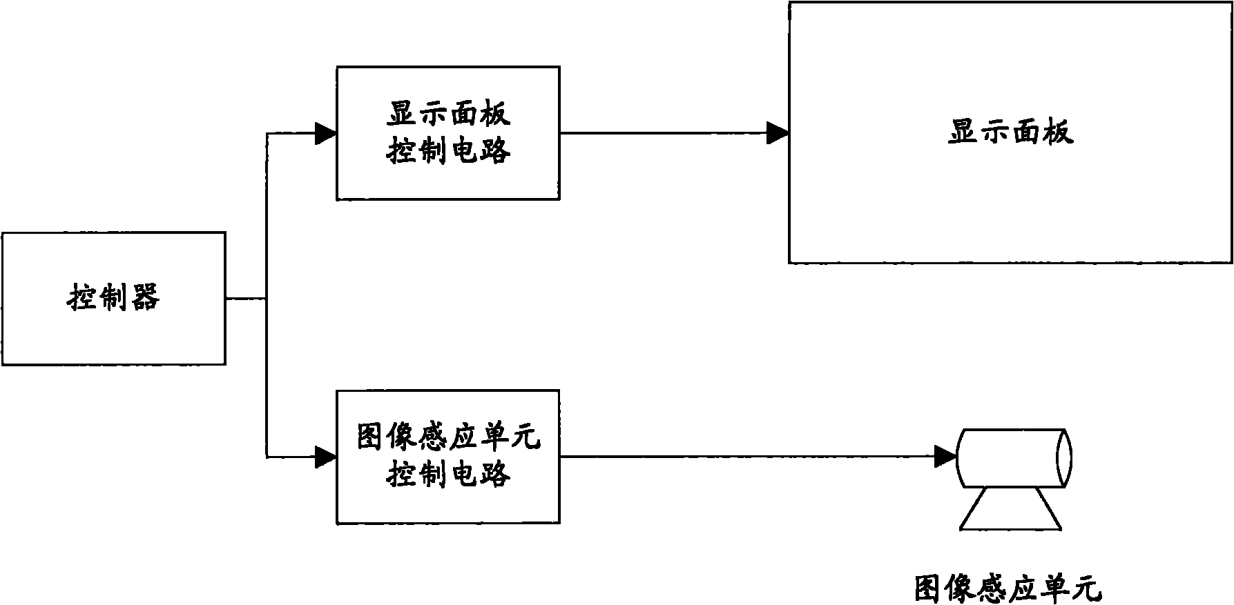
[0038] In this embodiment, a system for adjusting the position of an image sensing device will be described, taking a camera as an example. Figure 6A schematic diagram showing a mechanical mechanism according to an exemplary embodiment of the present invention. Wherein, the camera is placed on a platform controlled by a stepping motor, and the movement of the camera can be controlled by the stepping motors of the X and Y axes. That is, according to the coordinates obtained from the target position described in the first embodiment or the second embodiment, the camera can be moved by the X-axis motor and the Y-axis motor.

[0039] Specifically, the coordinates of the target position are converted into X and Y axis coordinates and sent to the stepping motors respectively, and the stepping motor adjusts the camera to the area corresponding to the target position according to the X and Y coordinates.

[0040] In addition, the mechanical mechanism can also be used for multiple im...


PUM


Abstract

The invention provides an adjustable image display and acquisition device which comprises a display panel, a display control module and one or a plurality of image sensing unit(s), wherein the display panel is used for display the image; the display control module is used for switching between an opening state and a closing state at the preset frequency; when the control module is in the opening state, the display panel displays the image; when the control module is in the closing state, at least part of the display panel is closed and transparent; the image sensing unit(s) is/are arranged at the back side of the display panel towards the display side of the display panel; and when in a working state, the image sensing unit(s) is/are used for acquiring the image when at least part of the display panel is transparent, and can be adjusted at the position corresponding to the base side of the display panel.

Description

technical field [0001] The invention relates to an image display and acquisition device, in particular to an adjustable image display and acquisition device. Background technique [0002] The current display and camera are separate devices, and there is a trend that more and more displays will integrate cameras, just like notebooks currently do. However, the current camera is generally integrated directly above or on the side of the display, and the user's line of sight is looking into the screen, so the camera cannot capture the image of the operator looking directly at it. [0003] To collect the user's front-view image, the existing common method is that multiple cameras capture the side images of multiple users, and then synthesize the front face image through an image algorithm. However, since the position of the user and the display is very close, and the size of the display tends to be larger and larger, unless the user keeps focusing on the middle of the display scr...

Claims


Application Information

Patent Timeline
IPC IPC(8): G06F1/16G09G5/00G06K9/00
Inventor 姜珊
Owner LENOVO (BEIJING) CO LTD
Why Eureka
Try Eureka