
Autoinjector with trigger positionable in active position by movement of a safety shield and indication of the active position

A technology of automatic injection and triggering device, which is applied in the directions of automatic injectors, syringes, hypodermic injection devices, etc., can solve the problems of difficulty in determining the positioning of the self-injection device, difficulty in determining the shell, and pain of patients, and achieves the effect of preventing misuse

Active Publication Date: 2010-10-06
BECTON DICKINSON FRANCE
View PDF0 Cites 24 Cited by
  • Summary
  • Abstract
  • Description
  • Claims
  • Application Information

AI Technical Summary

Problems solved by technology

[0006] However, it has proven difficult for the end user to determine if the self-injecting device is correctly positioned at the injection site
In particular, when the insertion and injection of the needle is only actuated after the distal end of the device is placed on the skin and the housing of said device has been pushed towards the injection site, it is difficult to determine whether the housing has been pushed towards the skin to a sufficient extent, especially Because the skin is slightly tensed at the injection site and because exerting such a distal force on the device is painful for the patient who does not feel the device properly on their skin

Method used


Image

  • Autoinjector with trigger positionable in active position by movement of a safety shield and indication of the active position
  • Autoinjector with trigger positionable in active position by movement of a safety shield and indication of the active position
  • Autoinjector with trigger positionable in active position by movement of a safety shield and indication of the active position

Examples


Embodiment Construction

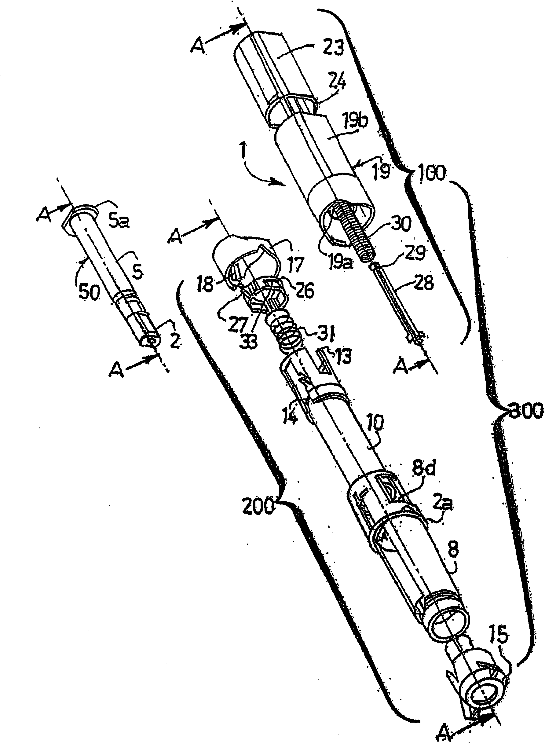
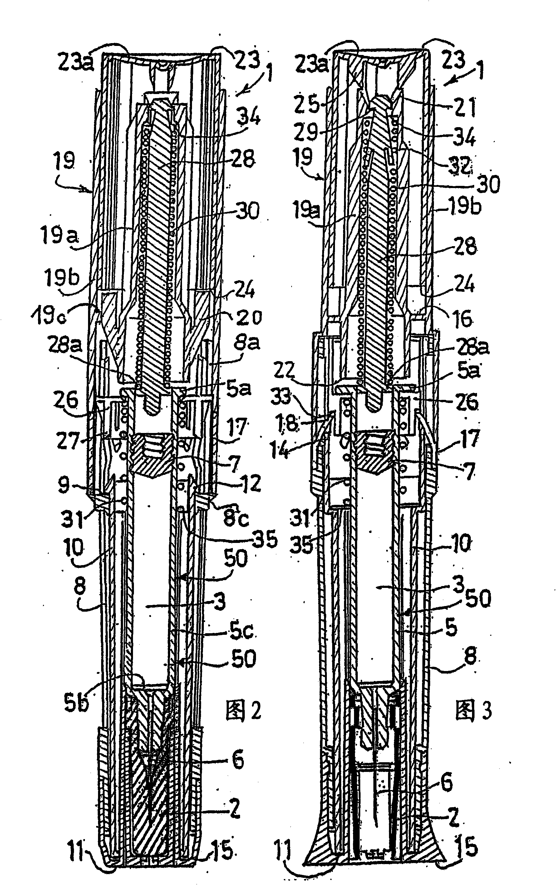
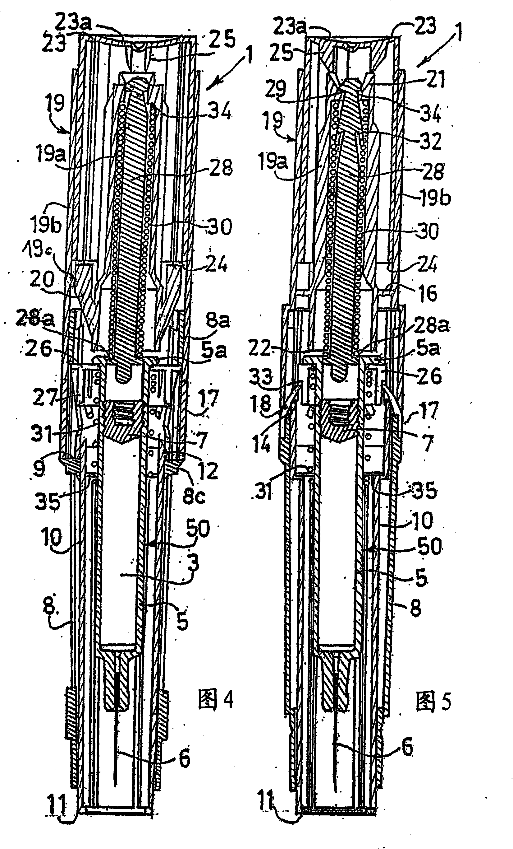
[0037] The present invention will now be described in detail with reference to the accompanying drawings. figure 1 An exploded perspective view of an automatic injection device according to an embodiment of the invention and generally indicated by reference numeral 1 is shown. The device 1 of the present invention comprises a housing 300 composed of an upper housing assembly 100 and a lower housing assembly 200, which can be connected by means of snap fit, threaded connection, bayonet connection Or other means of connecting two parts together to each other in a releasable or non-releasable manner. When the injection device is disposable, the user cannot touch the means for connecting the upper housing assembly 100 to the lower housing assembly 200 . A container 50 such as a syringe is received within at least one of the upper housing assembly 100 and the lower housing assembly 200 . Preferably, container 50 is partially received within each of upper housing assembly 100 and ...


PUM


Abstract

The invention relates to an automatic injection device (1) for a product contained in a container (50), comprising: - a housing (8, 19) receiving the container (50), the container being movable between an initial position and an insertion position, - triggering means (23) for initiating the movement of said container (50) from its initial position to its insertion position, said triggering means (23) being in one of a passive state, in which application of a force on said triggering means does not initiate movement of said container (50), and an active state, in which application of said force on said triggering means does initiate said movement, and - a safety shield (10) movable with respect to said housing (8, 19) between a first position and a second position, movement of said safety shield (10) from its first position to its second position placing said triggering means (23) in its active state, characterized in that said device comprises: an indicator (19c, 13) that provides an indication to a user of the device (1) that the safety shield (10) has reached its second position.

Description

technical field [0001] The present invention relates to a device for the automatic injection of a product, in particular for self-injection, in a very safe manner. Background technique [0002] In this application, the distal part of a component or device refers to the end farthest from the user's hand, and the proximal part refers to the end closest to the user's hand. Likewise, in the present application, "distal direction" refers to the direction of injection, and "proximal direction" refers to the direction opposite to the direction of injection. [0003] Some diseases require, for example, timed injections of drugs or products on a daily basis. To simplify treatment, some auto-injectors have been provided to allow patients to administer the injections themselves. [0004] Of course, since the patient is neither a nurse nor an educated person in the field of medical devices, it must be shown that this self-injector is very easy to use and very safe. In particular, the...

Claims


Application Information

Patent Timeline
IPC IPC(8): A61M5/20
CPCA61M5/326A61M2005/208A61M5/2033A61M2205/582A61M2005/3107A61M2205/581A61M5/3202A61M2005/206A61M5/3204A61M2005/3264A61M2005/2013
Inventor L·马里唐
Owner BECTON DICKINSON FRANCE
Learn More