
Sampling device and method for preparing the same

a sampling device and a technology for preparing the same, applied in the field of sampling devices, can solve the problems of not liking the idea, difficult to remove the introduction guide member, and complicated sampling procedures, and achieve the effect of preparing the sampling devi

Active Publication Date: 2019-10-22
ROVERS HLDG
View PDF21 Cites 1 Cited by
  • Summary
  • Abstract
  • Description
  • Claims
  • Application Information

AI Technical Summary

Benefits of technology

The patent is about a sampling device that can be used for self-sampling or by others, such as a physician. The device has a special brush with flexible bristles that are retracted in a tube to prevent damage to the vaginal walls during insertion. The device is easy to use, with measures to prevent discomfort or incorrect results. It allows for easy inspection and replacement of different brushes, and can be used in various combinations. Overall, this device provides a comfortable and reliable method for sample collection.

Problems solved by technology

Many women do not like the idea of such a sampling, because they do not feel comfortable with such a procedure.
The sampling procedure is very complicated, however.
However, due to the wide head 32 and the wide support member 23, both of which form an integral part of the stick, it is not possible to remove the introduction guide member 20 from the insertion tube 2.
Also, due to the wide aligning members, both of which form an integral part of the stick 55, it is not possible to insert the cervical sampler into the insertion tube 2.
The device described in WO 03 / 026502 is thus ineffective and can therefore not function as described in WO 03 / 026502.
However, if the sampler 50 is rotated during taking of the sample—as instructed—then the sample-collecting member can be retracted into the insertion tube and thus lose contact with the tissue to be sampled.
Reliable sampling can therefore not be guaranteed.
In addition, the design of the clicking system is such that pubic hair can easily become trapped in it, which may lead to painful results during rotation, which may in turn adversely affect the reliability of the sampling.
This is not only impractical and unpleasant, but also means that the tissue to be sampled will be pushed forcefully.
This is unpleasant and can lead to unreliable sampling.

Method used


Image

  • Sampling device and method for preparing the same
  • Sampling device and method for preparing the same
  • Sampling device and method for preparing the same

Examples


Embodiment Construction

[0066]It should be noted that with the sampling device 101 according to the invention illustrated in FIG. 5, the same reference numerals have been used as in the embodiment according to FIGS. 1-4, but increased by 100. So, for example: reference numeral 104 in FIG. 5 corresponds to reference numeral 4 in FIGS. 1-4, with both 104 and 4 denoting the plunger.

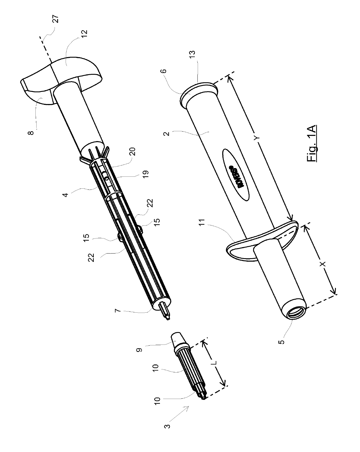
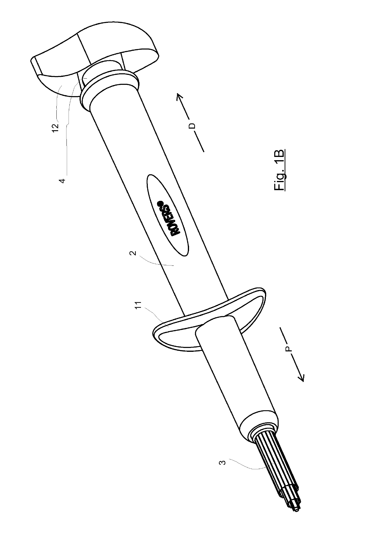
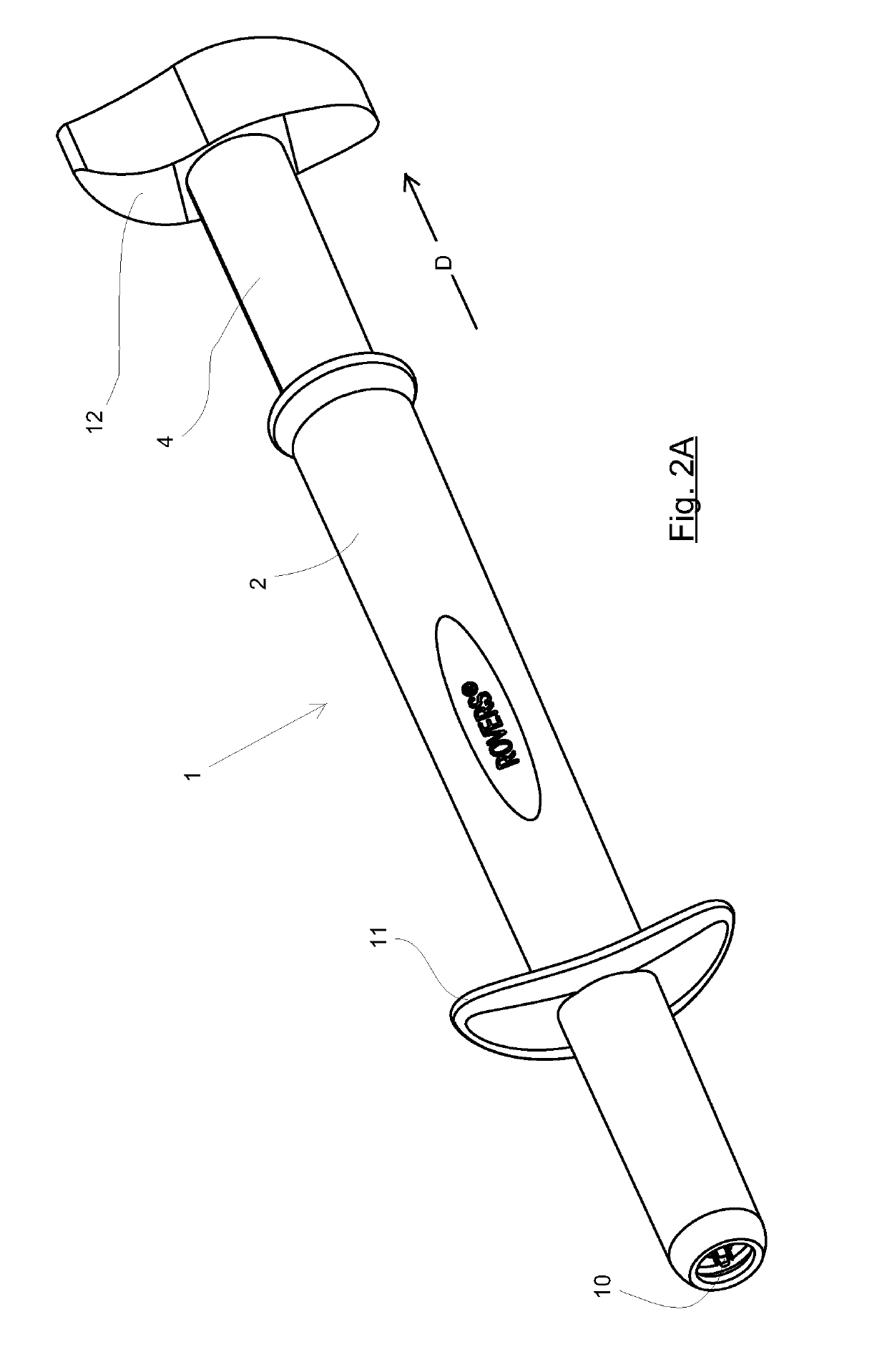
[0067]FIG. 1 shows a sampling device 1 according to the invention with the parts separated—FIG. 1A—and in the assembled state—FIG. 1b. According to all aspects of the invention:[0068]the sampling device 1 comprises a tube 2, a sampling member 3 and a plunger 4 having a longitudinal axis 27;[0069]the tube 2 has an open proximal tube end 5 and an open distal tube end 6;[0070]the plunger 4 has a proximal plunger end 7 and distal plunger end 8; and[0071]the proximal plunger end 7 carries, optionally in a detachable manner, the sampling member 3.

[0072]In the assembled state, the plunger 4 is inserted in the tube 2 and the plunger end 8 ...


PUM


Abstract

The present invention relates to a sampling device for sampling a body cavity, in particular for sampling the vagina and / or cervix. The sampling device comprises a tube having two open ends, a sample-collecting member and a plunger. The plunger is inserted in the tube, with the distal plunger end protruding from the distal tube end, and carries the sample-collecting member at the proximal tube end. The plunger is displaceable in the proximal direction in the tube from a retracted introduction position into an extended sampling position. In the introduction position, the sampling member is situated inside the tube and protrudes from the tube in the sampling position.

Description

BACKGROUND OF THE INVENTIONField of the Invention[0001]The present invention relates to a sampling device for sampling a body cavity, in particular for sampling the vagina and / or cervix.Description of the Related Art[0002]Such sampling devices are known. Examples which may be mentioned include, inter alia, the Cervex-Brush®, the EndoCervex-Brush® and the Viba-Brush®, which are all marketed by Rovers Medical Devices B.V. (NL).[0003]The Viba-Brush® is a brush having a plurality of relatively long brush hairs which extend in the axial direction. One end of each of these brush hairs is fixed on the hair carrier, while the other end protrudes forward freely in the proximal direction. Together, the hairs form a bundle of hairs which extend mutually parallel. In the horizontal position—when the brush hairs extend horizontally—these hairs continue to extend substantially horizontally; each of them forms a so-called ‘cantilever beam’. These brush hairs do not have to be supported, as, due to...

Claims


Application Information

Patent Timeline
Patent Type & Authority Patents(United States)
IPC IPC(8): A61B10/04A61B10/02A61B17/00A61B90/00A61B17/42
CPCA61B10/04A61B10/0291A61B10/02A61B2090/034A61B2017/4216A61B2090/036A61B2017/00115A61B2010/0216
Inventor ZWART, MEINDERT DURK
Owner ROVERS HLDG
Learn More