
Pulverized coal combustion system with porous wall wind coupled air classification

A technology of air classification and pulverized coal combustion, applied in burners, combustion chambers, combustion methods, etc., can solve the problems of high temperature corrosion of water-cooled walls, aggravated heat absorption deviation of heating surfaces, safety accidents, etc., to prevent high temperature corrosion and eliminate absorption. Thermal deviation, contamination reduction effect

Active Publication Date: 2016-01-20
TAIYUAN UNIV OF TECH
View PDF5 Cites 0 Cited by
  • Summary
  • Abstract
  • Description
  • Claims
  • Application Information

AI Technical Summary

Problems solved by technology

Pulverized coal air staged combustion technology is very effective in reducing nitrogen oxide emissions, but it also has the following disadvantages: 1) The water wall is prone to high temperature corrosion
2) Reduced combustion efficiency of pulverized coal
However, the introduction of the wall-attached wind often leads to the following problems: 1) The wall-attached wind is horizontal and parallel to the water-cooled wall, which is an ineffective wind for pulverized coal combustion and cannot improve the combustion efficiency; 2) The wall-attached wind is Concentrated air supply, uneven distribution in the furnace, resulting in uneven distribution of smoke temperature and smoke velocity at the furnace outlet, aggravating the heat absorption deviation of the heating surface, and easily causing safety accidents
There are two reasons for the above-mentioned problems caused by the wall-attached wind: 1) The wind direction is parallel to the water-cooled wall, so that it cannot participate in the combustion of pulverized coal; 2) The air distribution method of centralized air intake causes uneven distribution of the air distribution in the furnace

Method used


Image

  • Pulverized coal combustion system with porous wall wind coupled air classification

Examples


Embodiment Construction

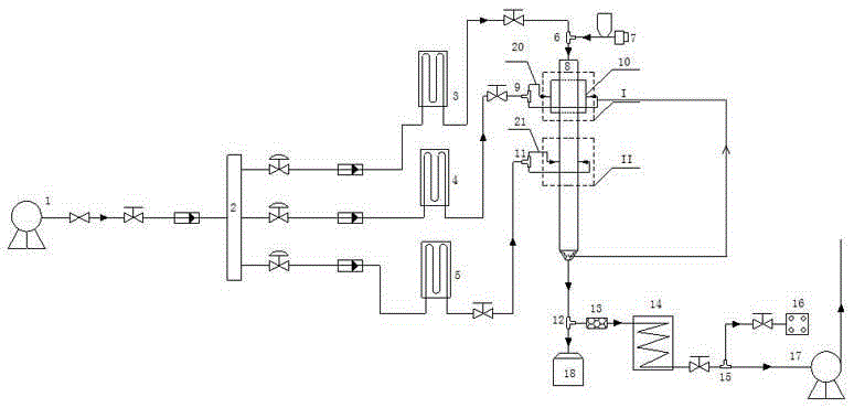
[0012] refer to figure 1 , the pulverized coal combustion system with porous wall wind coupling air staging, including air compressor 1, air distribution box 2, first air preheater 3, second air preheater 4, third air preheater 5, first Three-way joint 6, powder feeder 7, porous wall coupled air classification combustion reactor 8, second three-way joint 9, air chamber 10, third three-way joint 11, fourth three-way joint 12, pipeline filter 13, Flue gas cooler 14, fifth tee joint 15, flue gas analyzer 16, induced draft fan 17, ash pool 18. The outlet of blower 1 is connected to the inlet of air distribution box 2 after passing through the pressure reducing valve, stop valve and air flow meter; the outlet of air distribution box 2 is three air branches, and the first branch passes through the regulating valve and air flow on the branch. After the flow meter, it is connected to the inlet of the first air preheater 3, and the outlet of the first air preheater 3 is connected to a...


PUM


Abstract

The invention belongs to the field of clean and efficient combustion of coil and particularly relates to a pulverized coal combustion system with porous wall wind coupled air classification. According to the pulverized coal combustion system with porous wall wind coupled air classification, a mixture of air and pulverized coal enters the top of a combustion furnace and is ignited and burnt, the mixture passes a porous wall wind coupling portion from top to bottom for combustion, through combustion of a complete combustion portion, exhaust gas and waste slag are discharged from the bottom of the furnace and separated, flying ash of the separated exhaust gas is filtered out through a filter, and the exhaust gas is cooled through a cooler, detected through a smoke analyzer and finally exhausted to the environment. A wall face can be protected through porous wall wind and high-temperature corrosion is prevented; the porous wall wind is perpendicularly blown to a hearth, the mixing effect of the pulverized coal and the air is enhanced, and pulverized coal combustion is promoted.

Description

technical field [0001] The invention belongs to the field of clean and high-efficiency coal combustion, in particular to a pulverized coal combustion system with porous wall wind coupled with air classification. Background technique [0002] The air staged combustion technology of pulverized coal is the most widely used low-NOx combustion technology, which is characterized by introducing part of the air required for combustion (also known as separated overburning air) from an appropriate distance from the main burner, so that the combustion area Split into an oxygen-lean combustion zone (also known as a reduction zone) and an oxygen-enriched zone. Pulverized coal air staged combustion technology is very effective in reducing nitrogen oxide emissions, but it also has the following disadvantages: 1) The water wall is prone to high temperature corrosion. Using air staged combustion, the oxygen-poor combustion zone of the furnace produces a large amount of reducing substances s...

Claims


Application Information

Patent Timeline
IPC IPC(8): F23D1/00F23M5/00F23L9/00F23J1/00
Inventor 马红和周璐范江马素霞崔志刚贾涛尚福栋欧聪
Owner TAIYUAN UNIV OF TECH
Learn More