
Little oil ignited swirling pulverized coal combustion device

A pulverized coal combustion and low-oil ignition technology, which is applied in the direction of using multiple fuels for combustion, combustion ignition, and combustion methods, can solve the problems of energy waste, large oil consumption, and high pollutant emissions from coal-fired boilers

Inactive Publication Date: 2008-05-28
HARBIN INST OF TECH
View PDF0 Cites 5 Cited by
  • Summary
  • Abstract
  • Description
  • Claims
  • Application Information

AI Technical Summary

Problems solved by technology

[0003] The purpose of the present invention is to provide a low-oil ignition swirling pulverized coal combustion device to solve the problems of large oil consumption, energy waste, and high pollutant discharge of coal-fired boilers in existing power station coal-fired boiler combustion devices

Method used


Image

  • Little oil ignited swirling pulverized coal combustion device

Examples


specific Embodiment approach 1

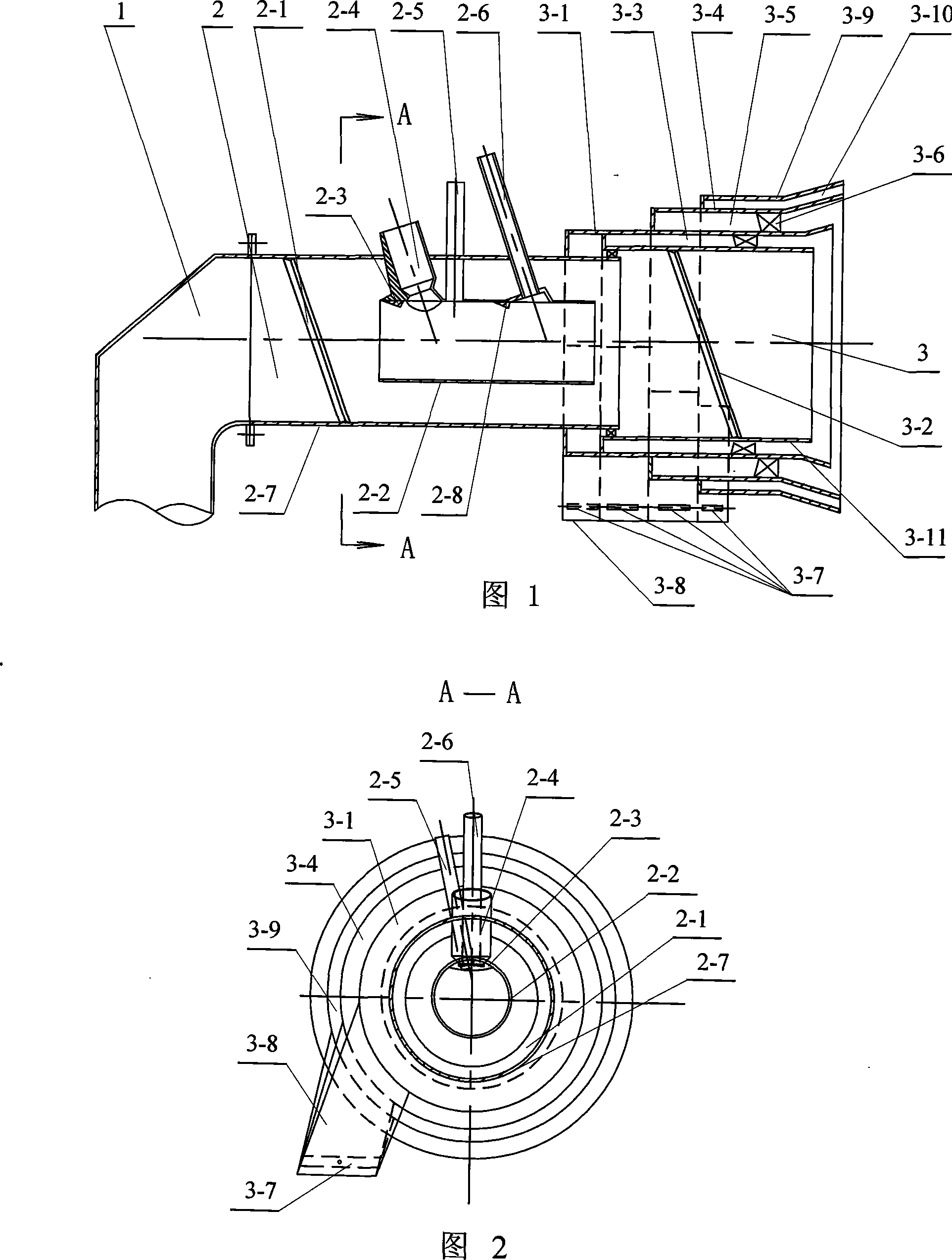
[0005] Specific embodiment one: (see Fig. 1, Fig. 2) present embodiment is made up of coal-fired ignition device 2 and graded burner 3, and coal-fired ignition device 2 is made up of oil, coal burner pipe 2-2, main fuel oil pipe 2- 4. Composed of fire detection pipe 2-5, auxiliary fuel pipe 2-6 and outer pipe 2-7, oil and coal burner pipe 2-2 is set on the outlet side of outer pipe 2-7, main fuel pipe 2-4 The outlet end of the main fuel pipe 2-4 is fixedly connected with the outer pipe 2-7, and the outlet end of the auxiliary fuel pipe 2-6 is connected with the oil and coal burner pipe 2-2. One side of the outlet end of the burner pipe 2-2 is connected, the middle part of the auxiliary fuel pipe 2-6 is fixedly connected with the outer pipe 2-7, and the flame detection pipe 2-5 is arranged on the main fuel pipe 2-4 and the auxiliary fuel pipe 2- 6, one end of the flame detection pipe 2-5 is connected with the oil and coal burner pipe 2-2, and the middle part of the flame detect...

specific Embodiment approach 2

[0006] Specific embodiment two: (referring to Fig. 1, Fig. 2) the difference between this embodiment and specific embodiment one is that the cross-sectional area of ​​the oil and coal burner pipe 2-2 inlet end is less than the cross-sectional area of ​​the outlet end. Other compositions and connections are the same as in the first embodiment. Changing the structure of the oil and coal burner tube 2-2 can make the pulverized coal gradually diffuse and fully mix with the oxygen added by the swirling wind on the inner wall, which is beneficial to the combustion and the fullness of the flame at the outlet of the pulverized coal combustion device.

specific Embodiment approach 3

[0007] Specific embodiment three: (referring to Fig. 1, Fig. 2) the difference between this embodiment and specific embodiment one is that the cross-sectional area of ​​the oil and coal burner pipe 2-2 outlet end is equal to the cross-sectional area of ​​the inlet end. Other compositions and connections are the same as in the first embodiment. Changing the structure of the oil and coal burner tube 2-2 can increase the amount of concentrated coal powder and reduce the amount of air, so that the burning coal powder is gradually diffused and fully mixed with the oxygen added by the swirling wind on the inner wall.


PUM


Abstract

A low-oil-consumption ignition swirling pulverized coal burning device relates to a pulverized coal burning device. The invention aims to solve the problems of large oil consumption, energy waste, and high pollutant discharge of a coal-fired boiler existing in the burning device in the coal-fired boiler of power plants. An inlet end of an inner wall swirling wind cover (3-1) in the invention is connected with an outlet end of an external pipe (2-7), a passage exit in a duct (3-8) is respectively connected with the inner wall swirling wind cover (3-1), a swirling outer secondary wind cover (3-4) and a direct secondary wind cover (3-9), and the passage exist in the duct (3-8) is respectively provided with an air volume regulation plate (3-7). The invention has the advantage of reasonable structure, design and arrangement. The invention burns pulverized coal by using a small amount of oil, oil and gas, natural gas or coal gas, which can save ignition energy, and reduces the discharge of pollutant. The device of the invention has higher safety and reliability properties, which can save 40%-90% fuel oil compared with the prior art.

Description

technical field [0001] The invention relates to a pulverized coal combustion device. Background technique [0002] The arrangement of the combustion device and the ignition oil gun of the existing power station coal-fired boiler has the following forms: 1. The combustion device and the ignition oil gun are arranged separately, and the ignition oil gun is arranged on the coal-fired burner of the boiler, but the nozzle of the ignition oil gun points to the furnace 2. The oil gun is arranged in the nozzle of the burner, which can adopt mechanical atomization or steam atomization. The above two kinds of combustion devices and ignition oil guns have problems such as large amount of fuel, waste of energy, and high pollutant discharge of coal-fired boilers. Contents of the invention [0003] The purpose of the present invention is to provide a low-oil ignition swirling pulverized coal combustion device to solve the problems of large oil consumption, energy waste, and high pollut...

Claims


Application Information

Patent Timeline
IPC IPC(8): F23C5/32F23Q2/00
Inventor 陈力哲孙锐吴少华
Owner HARBIN INST OF TECH
Learn More