Device for preventing high-temperature corrosion of water cooling wall of combustion boiler and boiler corrosion prevention method

A high-temperature corrosion and water-cooled wall technology, which is applied in the fields of boiler anti-water-cooled wall high-temperature corrosion prevention device and boiler anti-corrosion, combustion boiler anti-water-cooled wall high-temperature corrosion device and boiler anti-corrosion field, can solve boiler side wall water-cooled wall high-temperature corrosion and other problems, To achieve the effect of strengthening the oxidizing atmosphere near the wall, reducing the possibility and reducing the impact

Active Publication Date: 2021-12-10
HARBIN INST OF TECH
View PDF9 Cites 4 Cited by
  • Summary
  • Abstract
  • Description
  • Claims
  • Application Information

AI Technical Summary

Problems solved by technology

[0005] The purpose of the present invention is to solve the problem that the existing boiler uses a central powder-feeding swirl pulverized coal burner in the main combustion area of ​​the front and rear walls, and removes the fins of the water-cooled walls on both sides to form a gap, and blows the secondary air in from the gap. Furnace and boiler side wall water wall still have high temperature corrosion problems, and then provide a device for preventing high temperature corrosion of the water wall of the combustion boiler and a boiler anti-corrosion method

Method used


Image

  • Device for preventing high-temperature corrosion of water cooling wall of combustion boiler and boiler corrosion prevention method
  • Device for preventing high-temperature corrosion of water cooling wall of combustion boiler and boiler corrosion prevention method
  • Device for preventing high-temperature corrosion of water cooling wall of combustion boiler and boiler corrosion prevention method

Examples


specific Embodiment approach 1

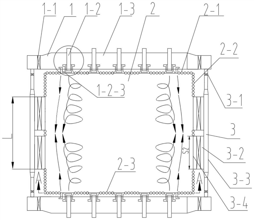
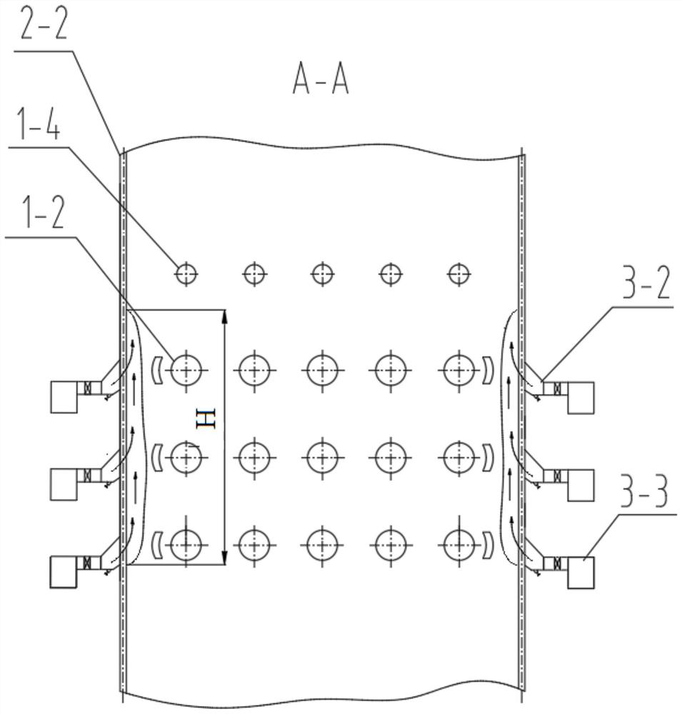
[0048] Specific implementation mode one: combine Figure 1-Figure 7 To illustrate this embodiment, the combustion boiler prevents high-temperature corrosion of the water wall, which includes a combustion system 1, a furnace 2 and two sets of wall-attached air systems 3; the furnace 2 includes a front wall 2-1, a rear wall 2-3 and Two side walls 2-2, the combustion system 1 includes two secondary air doors 1-1, two secondary air boxes 1-3, multiple burners 1-2 and multiple overfire air ports 1-4, The front wall 2-1, the rear wall 2-3 and two side walls 2-2 form the boiler body, the front wall 2-1 and the rear wall 2-3 are arranged oppositely, the two side walls 2-2 are arranged oppositely, and one secondary Damper 1-1 is installed on the front wall 2-1, and another secondary air door 1-1 is installed on the back wall 2-3, and a secondary air bellows 1-3 and a plurality of combustion air boxes 1-3 are installed on the front wall 2-1 A secondary air box 1-3 and a plurality of bu...

specific Embodiment approach 2

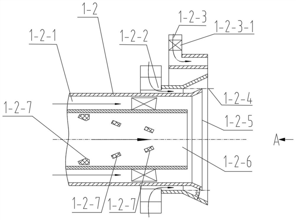
[0049] Specific implementation mode two: combination figure 1 and image 3 Describe this embodiment, the high-temperature corrosion prevention device for the water wall of the combustion boiler described in this embodiment, the burner 1-2 includes an inner secondary air swirler 1-2-1, an outer secondary air swirler 1-2-2 , Outer secondary air nozzle 1-2-4, inner secondary air nozzle 1-2-5, primary air pipe 1-2-6 and three conical pulverized coal separators 1-2-7; three conical The pulverized coal separator 1-2-7 is arranged in the primary air pipe 1-2-6 along the length direction, and the inner secondary air nozzle 1-2-5 and the outer secondary air nozzle 1-2-4 are arranged in sequence from the inside to the outside Outside the primary air duct 1-2-6, the inner secondary air cyclone 1-2-1 is installed inside the inner secondary air nozzle 1-2-5 outside the primary air duct 1-2-6, and the outer secondary air The wind cyclone 1-2-2 is installed at the outer secondary air nozzl...

specific Embodiment approach 3

[0050] Specific implementation mode three: combination figure 1 and image 3 To illustrate this embodiment, the device for preventing high-temperature corrosion of the water-cooled wall of the combustion boiler described in this embodiment also includes a plurality of offset high-temperature corrosion-resistant air ducts 1-2-3; the offset high-temperature corrosion-resistant air ducts 1-2-3 are Arc-shaped pipe, air door 1-2-3-1 is installed on the offset high-temperature corrosion-resistant air duct 1-2-3, and the offset high-temperature corrosion-resistant air duct 1-2-3 is installed on both sides of the front wall 2-1 close to On the burner 1-2 at the position of the side wall 2-2, the offset high-temperature corrosion-resistant air duct 1-2-3 is installed on both sides of the rear wall 2-3 close to the burner 1-2 at the position of the side wall 2-2. Other compositions and connection methods are the same as those in the second embodiment.


PUM


Abstract

The invention discloses a device for preventing high-temperature corrosion of a water cooling wall of a combustion boiler and a boiler corrosion prevention method, relates to the device for preventing high-temperature corrosion of the water cooling wall of the boiler and the boiler corrosion prevention method, and aims to solve the problem that a central powder feeding rotational flow pulverized coal burner is used in a front and rear wall main combustion area of an existing boiler. The device comprises a combustion system, a hearth and two groups of close-to-wall air systems, wherein the hearth comprises a front wall, a rear wall and two side walls; the combustion system comprises two secondary air doors, two secondary air boxes, multiple combustors and multiple over-fire air ports; and the front wall, the rear wall and the two side walls form a boiler body. The method is implemented according to the following steps: 1, ventilation is conducted in the secondary air boxes; 2, wall-attaching wind is added to the side walls; and 3, the high-temperature corrosion prevention direct-current air in the first step and the wall-attaching wind in the second step act jointly, so that the high-temperature corrosion phenomenon of the water cooling wall is prevented, and the purpose of the invention is achieved. The invention belongs to the field of boilers.

Description

technical field [0001] The invention relates to a device for preventing high-temperature corrosion of a water wall of a boiler and a method for preventing corrosion of a boiler, in particular to a device for preventing high-temperature corrosion of a water wall of a combustion boiler and a method for preventing corrosion of a boiler, belonging to the field of boilers. Background technique [0002] With the improvement of NOx emission standards, coal-fired power plants continue to strengthen the degree of air classification in the furnace, reduce the oxygen content of the main combustion zone, and increase the proportion of overfired air. High temperature corrosion problems are brought about. The front and rear walls of opposed combustion boilers account for a large proportion of power plant boilers in my country, and the high-temperature corrosion of the water-cooled wall in the main combustion zone of the side wall is particularly prominent. High-temperature corrosion of t...

Claims


Application Information

Patent Timeline
Patent Type & Authority Applications(China)
IPC IPC(8): F23C7/02F23L1/00F23L9/00
CPCF23C7/008F23C7/02F23L1/00F23L9/00Y02E20/34
Inventor 李争起黄椿朝姜广飞刘政陈智超
Owner HARBIN INST OF TECH
Why Eureka
Try Eureka