
Sampling device and method of preparing sampling device

一种取样装置、样本采集的技术,应用在医药科学、接种排卵诊断、手术等方向,能够解决不舒服、不可靠取样、不可行等问题

Active Publication Date: 2016-05-04
ROVERS HLDG
View PDF6 Cites 0 Cited by
  • Summary
  • Abstract
  • Description
  • Claims
  • Application Information

AI Technical Summary

Problems solved by technology

Not only is this infeasible and uncomfortable, but it means that the tissue to be sampled will be strongly pushed
This is uncomfortable and can lead to unreliable sampling

Method used


Image

  • Sampling device and method of preparing sampling device
  • Sampling device and method of preparing sampling device
  • Sampling device and method of preparing sampling device

Examples


Embodiment Construction

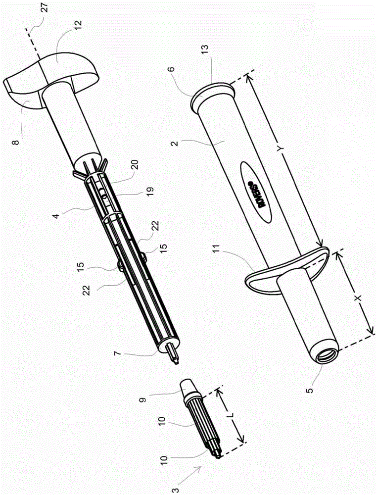
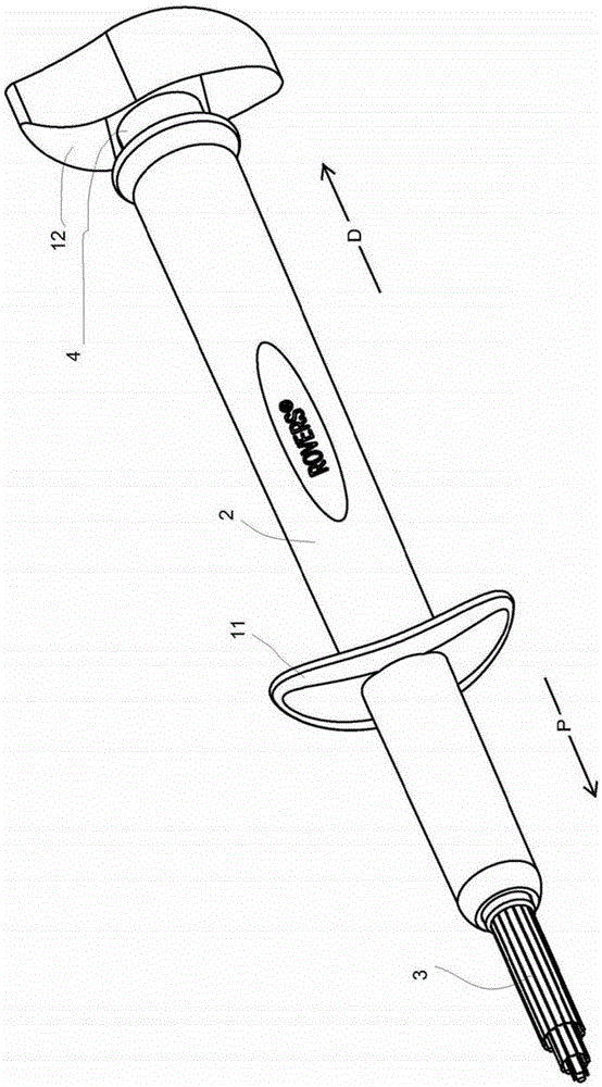
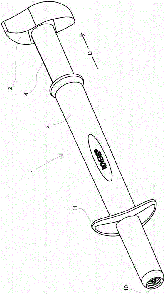
[0093] Figure 1 shows a sampling device 1 according to the invention, with separated parts ( Figure 1A ) and for the assembled state ( Figure 1B ). According to all aspects of this disclosure:

[0094] The sampling device 1 comprises a tube 2, a sample acquisition member 3, and a plunger 4 having a longitudinal axis 27;

[0095] the tube 2 has an open proximal tube end 5 and an open distal tube end 6;

[0096] the plunger 4 has a plunger proximal end 7 and a plunger distal end 8; and

[0097] • The plunger proximal end 7 carries (optionally in a detachable manner) the sample acquisition member 3 .

[0098] In the assembled state, the plunger 4 is inserted into the tube 2 and the plunger end 8 protrudes from the distal end of the tube. The plunger 4 is displaceable in the proximal direction P from a retracted introduction position (see FIG. 2 ) to an extended sampling position ( FIG. 3 ), in which the sample collection member 3 is inside the tube 2 , preferably completely...


PUM


Abstract

The invention relates to a sampling device for sampling a body cavity, in particular for sampling the vagina and / or the cervix. The sampling device includes a tube having two open ends, a sample collection member, and a plunger. The plunger is inserted into the tube with a plunger distal end protruding from the tube distal end, and the plunger carries a sample acquisition member at the tube proximal end. The plunger is displaceable in a proximal direction within the tube from a retracted introduction position to an extended sampling position. In the introduction position, the sampling member is located inside the tube and protrudes from the tube in the sampling position.

Description

technical field [0001] The present invention relates to a sampling device for vaginal and / or cervical sampling. Background technique [0002] Such sampling devices are known. Examples that may be mentioned include in particular as well as All of these are already marketed by Rovers Medical Devices B.V. (NL). [0003] said is a brush having a plurality of relatively long bristles extending in the axial direction. One end of each of these bristles is secured to the bristle carrier, while the other end freely protrudes forward in the proximal direction. The hairs together form a tuft of hairs that extend parallel to each other. In the horizontal position (when the bristles extend horizontally) these bristles continue to extend substantially horizontally; each of them forms a so-called "cantilever". These bristles do not have to be supported, since the bristles in this case form a cantilever beam, so that the bristles automatically continue parallel to each other and...

Claims


Application Information

Patent Timeline
Patent Type & Authority Patents(China)
IPC IPC(8): A61B10/02
CPCA61B10/02A61B2010/0216A61B2017/00115A61B2017/4216A61B2090/034A61B2090/036A61B10/0291A61B10/04
Inventor M·D·兹瓦特
Owner ROVERS HLDG
Learn More