Novel multistage centrifugal pump

A centrifugal pump and a new type of technology, applied in the field of centrifugal pumps, can solve the problems of easy to produce a hump in the lift curve, increase the outlet width, and reduce the pump efficiency, and achieve the effect of improving the performance range, reducing the leakage and improving the efficiency.

Inactive Publication Date: 2010-10-20
ZHEJIANG UNIV OF TECH
View PDF4 Cites 9 Cited by
  • Summary
  • Abstract
  • Description
  • Claims
  • Application Information

AI Technical Summary

Problems solved by technology

Cutting the outer diameter of the impeller is a common method to change the performance range of the pump, but when the outer diameter of the impeller is cut too much, the outlet width will become larger, and the actual head curve will easily produc

Method used


Image

  • Novel multistage centrifugal pump
  • Novel multistage centrifugal pump
  • Novel multistage centrifugal pump

Examples


Embodiment

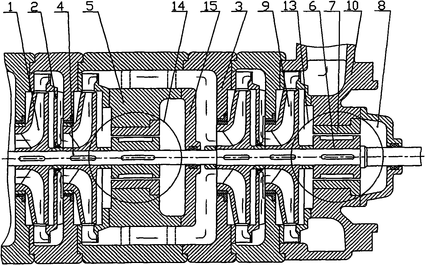
[0017] Example: such as figure 1 , the new multi-stage centrifugal pump includes a pump shaft 4, on which a set of impellers 1 and guide vanes 2 matched thereto are arranged, the flow channel between the impellers 1 is connected by the middle section 3, and the last stage impeller 9 is connected with a water spouting section 10, When the pump is running, the liquid is sucked into the pump from the inlet, and the velocity energy and pressure energy of the liquid are increased by the action of the impeller 1, and then enters the impeller of the next stage through the guide vane 2 and the middle section 3, and finally the liquid is pumped by the final stage The impeller 9 is discharged to the spouting section 10, where most of the speed energy is converted into pressure energy, and then sent out along the discharge pipeline.

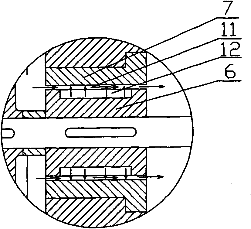
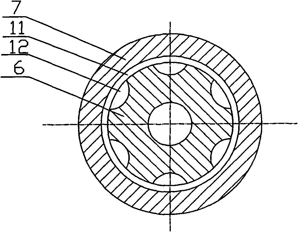
[0018] Wherein the rear side of the final stage impeller 9 is provided with a rear axial force balance device 13, such as figure 2 , 3 , consists of a b...


PUM


Abstract

The invention relates to a novel multistage centrifugal pump. A pump shaft is provided with a group of impellers and guide vanes. Runners among the impellers are communicated in the middle. A last stage impeller is connected with a water spray section. The rear side of the last stage impeller is provided with a post axial force balancing device. The post axial force balancing device consists of a balancing drum arranged on the pump shaft, a balancing drum sleeve sleeved outside the balancing drum and a balancing chamber, wherein a gap is reserved between the balancing drum and the balancing drum sleeve; and the surface of the balancing drum is provided with a plurality of axial grooves. The invention has the advantages that: (1) the leakage from the radial gap between the balancing drum and the balancing drum sleeve is small, so difference between front and rear pressures of the balancing drum is increased so large as to make the balancing of the axial force by the balancing drum convenient; (2) the novel multistage centrifugal pump is provided with a plurality of sets of axial force balancing device so as to meet balancing requirement of the axial force; and (3) the novel multistage centrifugal pump can improve the performance range of the pump, can avoid larger volume loss which occurs because the gap between the impeller and the guide vane is so large that the fluid cannot sufficiently enter the next stage impeller, and improves the efficiency of the pump.

Description

technical field [0001] The invention relates to a centrifugal pump, in particular to a novel multistage centrifugal pump. Background technique [0002] Multistage centrifugal pump is an important pump product widely used in various fields of national economic construction. Its axial force is very large, and some can even reach 10 5 N, unbalanced axial force is one of the main reasons for multi-stage pump failure. When the balance drum is used to balance the axial force, there will be a large leakage loss at the gap between the balance drum and the balance drum sleeve, and the axial force balance requirements cannot be met. However, if the leakage loss is reduced by reducing the gap, the balance drum and the balance drum The sleeves are easy to rub against each other, causing adverse effects such as equipment vibration. Multi-stage pumps usually have only one set of balancing devices, which are located behind the last stage impeller. For multi-stage pumps with many stages a...

Claims


Application Information

Patent Timeline
IPC IPC(8): F04D1/06F04D29/66F04D29/22
Inventor 牟介刚金建波郑水华赵永攀苏苗印汪慧赵锦靖陆河权
Owner ZHEJIANG UNIV OF TECH
Why Eureka
Try Eureka