Supercharge Your Innovation With Domain-Expert AI Agents!

Lens module

A technology of lens modules and optical components, applied in the direction of instruments, electrical components, circuits, etc., can solve the problems of affecting imaging quality, uneven force on optical components, affecting verticality, etc., and achieve the effect of improving imaging quality

Inactive Publication Date: 2010-10-20
HONG FU JIN PRECISION IND (SHENZHEN) CO LTD +1
View PDF3 Cites 6 Cited by
  • Summary
  • Abstract
  • Description
  • Claims
  • Application Information

AI Technical Summary

Problems solved by technology

However, since only a small part of the side wall of the optical component is under force, the force on the optical component is uneven, so after moving, it will affect the perpendicularity between the optical axis of the optical component and the sensing surface of the image sensor, thereby affecting image quality

Method used


Image

  • Lens module
  • Lens module
  • Lens module

Examples


Embodiment Construction

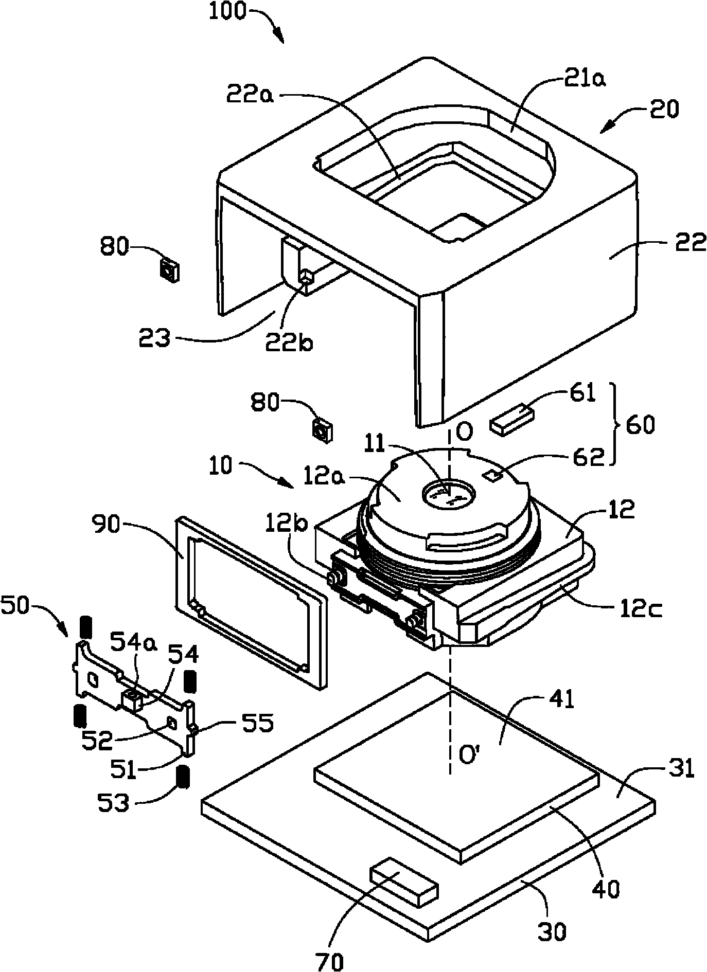
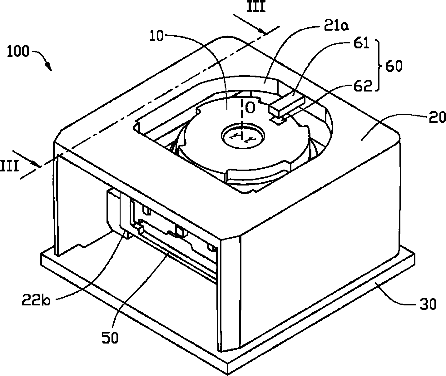
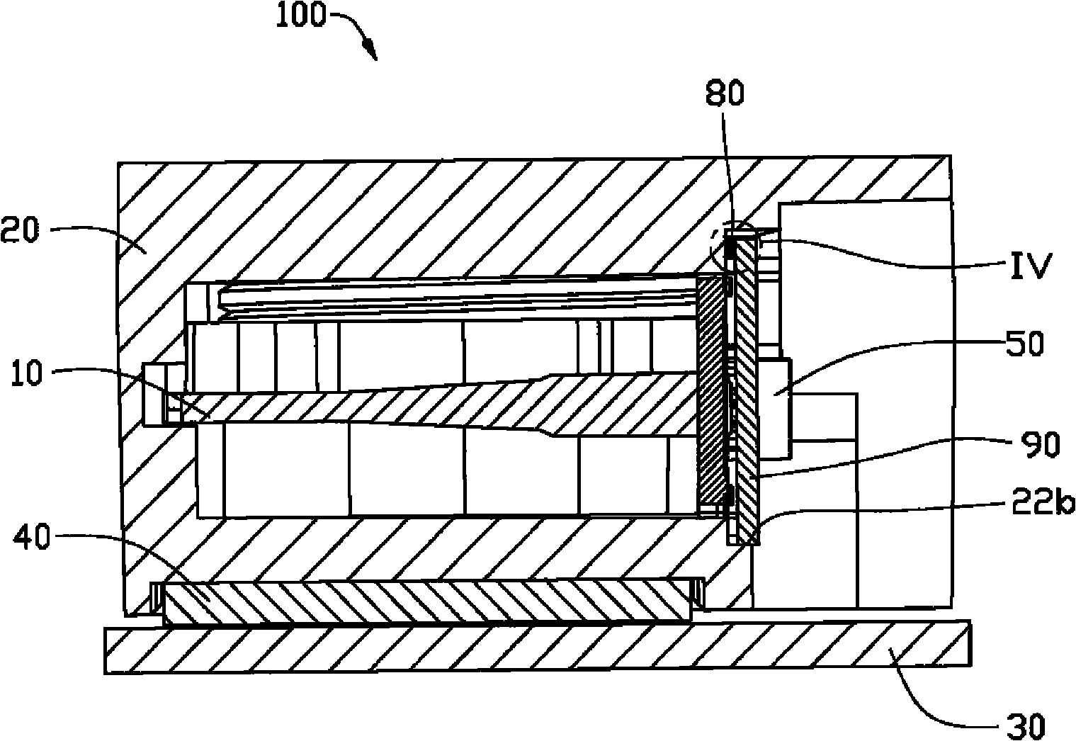
[0017] see figure 1 and figure 2 . The lens module 100 provided by the first embodiment of the present invention. In this embodiment, the lens module 100 is a zoom lens. The lens module 100 includes an optical component 10 , an accommodating case 20 , a circuit board 30 , an image sensor 40 , a connection board 50 , an optical inclination sensor component 60 , a controller 70 , an adjustment component 80 and a limit frame 90 .

[0018] The circuit board 30 includes a top surface 31 . The image sensor 40 has a sensing surface 41 . The image sensor 40 is fixed on the top surface 31 of the circuit board 30 . The accommodating shell 20 is substantially a cube, and the accommodating shell 20 includes a top plate 21 , a side wall 22 and an insertion opening 23 . The top plate 21 is processed with a light hole 21a, and the side wall 22 is processed with a slide groove 22a and a stepped structure 22b. The receiving case 20 is fixed on the top surface 31 of the circuit board 30...


PUM


Abstract

The invention provides a lens module, which comprises an optical component, a holding shell and an image sensor. The image sensor is provided with a sensing face, the optical component and the image sensor are arranged oppositely and are both held in the holding shell; the lens module also comprises an optical tilt-angle sensing component, a controller and at least one adjustment component, the optical tilt-angle sensing component detects the verticality of the optical axis of the optical component corresponding to the sensing face of the image sensor, the adjustment component is made from anelectrostrictive material and is connected between the optical component and the holding shell, and the flexible deformation of the electrified adjustment component can change the verticality of the optical axis of the optical component corresponding to the sensing face of the image sensor; the controller, the optical tilt-angle sensing component and the adjustment component are electrically connected, the controller can control the adjustment component to flex radially along the lens module according to the deflection level of the optical axis of the optical component detected by the opticaltilt-angle sensing component. In the invention, the imaging quality is improved through flexibly adjusting the verticality of the optical axis of the optical component corresponding to the verticality of the sensing face of the image sensor by the adjustment component.

Description

technical field [0001] The invention relates to a lens module. Background technique [0002] At present, while consumers require photographing devices, such as digital cameras and digital video cameras, to have better photographing quality, they also hope that these photographing devices are smaller and thinner. [0003] However, as the size of the lens module becomes smaller and smaller, in order to ensure the image quality, it is necessary to strictly control various factors that affect the image quality. Now when the optical assembly of the zoom lens module zooms, the cooperation between the drive shaft of the stepping motor and a small part of the side wall of the optical assembly is often used to drive the optical assembly to move along the optical axis. However, because only a small part of the side wall of the optical component is under force, the force on the optical component is uneven, so after moving, it will affect the perpendicularity between the optical axis o...

Claims


Application Information

Patent Timeline
Patent Type & Authority Applications(China)
IPC IPC(8): H01L27/146H01L31/0232G02B7/02H04N23/40
CPCG02B7/023G02B7/102H01L27/14618G02B7/005H01L2924/0002H01L2924/00
Inventor 颜士杰
Owner HONG FU JIN PRECISION IND (SHENZHEN) CO LTD
Features
  • R&D
  • Intellectual Property
  • Life Sciences
  • Materials
  • Tech Scout
  • Unparalleled Data Quality
  • Higher Quality Content
  • 60% Fewer Hallucinations
Learn More