Frequency hopping circuit for lightening CCFL and frequency hopping method thereof

A circuit and frequency hopping technology, which is applied in the control field of CCFL inverter circuit, can solve the problems of low gain, inability to ensure that CCFL is fully lit, and inability to guarantee switching frequency time of inverter circuit, etc., so as to reduce energy consumption and prolong working life Effect

Inactive Publication Date: 2010-10-27
CHENGDU MONOLITHIC POWER SYST
View PDF0 Cites 0 Cited by
  • Summary
  • Abstract
  • Description
  • Claims
  • Application Information

AI Technical Summary

Problems solved by technology

[0004] However, the switching frequency of the inverter circuit in this traditional method is at f open0 The time period below is a set time value, and it is possible that when the CCFL is lit, the switching frequency of the inverter circuit cannot be guaranteed to be at f open0 The time under it is long enough to ensure that the CCFL is completely lit; or when the CCFL is lit, the switching frequency of the inverter circuit is at f open0 The time is too long, and after the CCFL is lit, the inverter circuit still runs at the switching frequency f for a period of time open0 case, so that the CCFL is extinguished due to the low gain of the inverter circuit

Method used


Image

  • Frequency hopping circuit for lightening CCFL and frequency hopping method thereof
  • Frequency hopping circuit for lightening CCFL and frequency hopping method thereof
  • Frequency hopping circuit for lightening CCFL and frequency hopping method thereof

Examples


Embodiment Construction

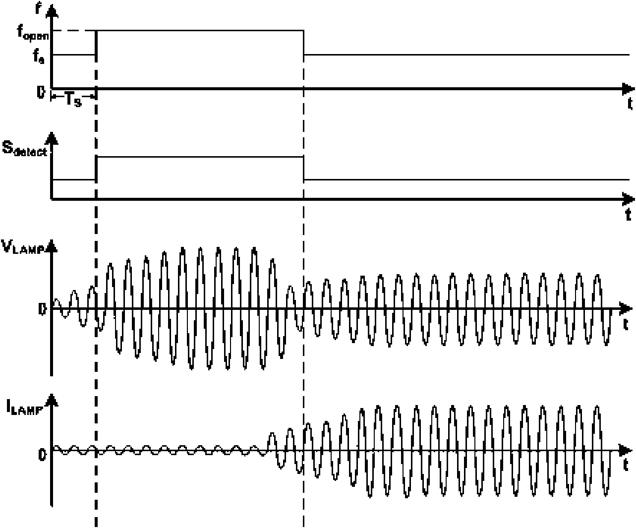
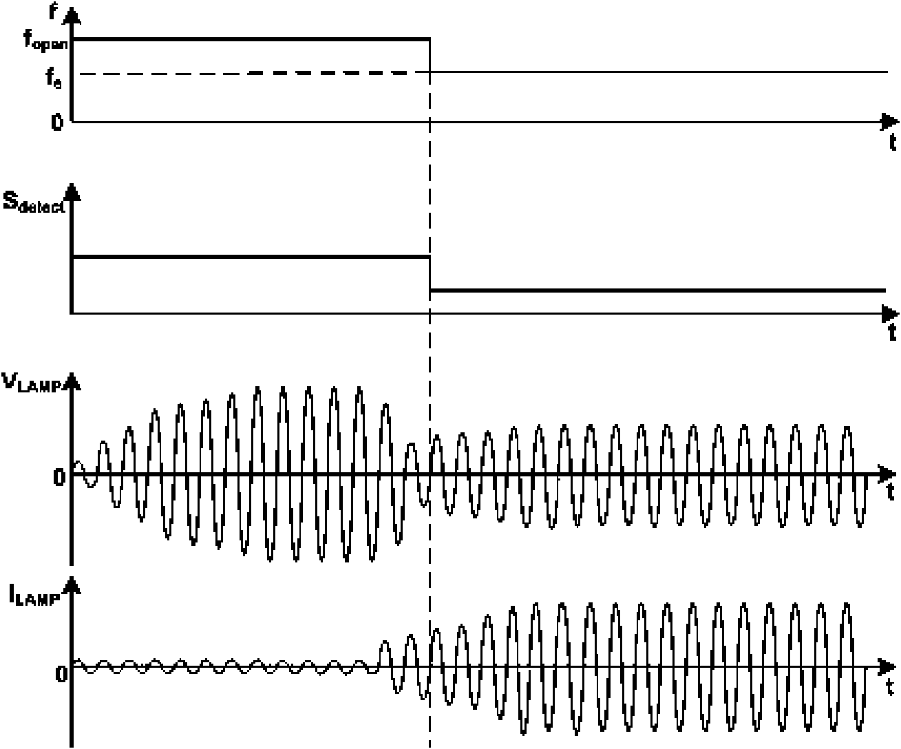
[0012] see figure 2 , is a waveform diagram of each signal of a frequency hopping circuit according to the present invention. Such as figure 2 As shown, the switching frequency f of the inverter circuit at the beginning is f s , after time period T S After that, the inverter circuit jumps its switching frequency f to its turn-on frequency f open , so that the gain is increased, thereby lighting the CCFL; when the lighting is completed, the inverter circuit jumps its switching frequency f back to its normal operating frequency f s . This process is determined by the lamp state detection signal S detect By detecting the current flowing through the CCFL I LAMP accomplish. When a current flowing through the CCFL is detected I LAMP is less than the first set value, and this situation lasts for a period of time T S , lamp state detection signal S detect It is judged that the CCFL is in an open state at this time, so the inverter circuit jumps its switching frequency f to...


PUM


Abstract

The invention provides a frequency hopping circuit for lightening a CCFL and a frequency hopping method thereof. The frequency hopping circuit comprises a frequency generator and a biasing circuit, wherein the biasing circuit comprises a first resistor, a second resistor, a DC biasing level and a switch; and the second resistor and the switch are connected in series and then are connected in parallel with the first resistor at two ends of the DC biasing level. The frequency hopping circuit meets the requirement on accurate frequency hopping in the process of starting the CCFL.

Description

technical field [0001] The invention relates to the control of CCFL (cold cathode fluorescent lamp) inverter circuit. Background technique [0002] The impedance of a CCFL is very different when it is open circuit and when it is operating normally when it is lit. Generally, when the CCFL is open, its impedance is quite large, and a large voltage needs to be applied across the CCFL to break it down and conduct it. And when it is in normal operation after it is lit, its impedance drops relatively low. At this time, it only needs to apply a small voltage to its two ends to ensure its normal operation. [0003] figure 1 It is the frequency gain curve of CCFL when it is open circuit and normal operation after being lit, where curve 1 is the frequency gain curve when it is lit and normal operation, and curve 2 is the frequency gain curve when it is open circuit. Generally, the switching frequency of the inverter circuit during normal operation is selected as the quasi-resonant ...

Claims


Application Information

Patent Timeline
Patent Type & Authority Applications(China)
IPC IPC(8): H05B41/295H05B41/36
CPCH05B41/282Y02B20/183Y02B20/00
Inventor 张军明蔡家利杜磊任远程杨先庆
Owner CHENGDU MONOLITHIC POWER SYST
Why Eureka
Try Eureka