Ejection mechanism for injection mould

A technology of ejecting mechanism and injection mold, applied in the field of ejecting mechanism, can solve the problems of low efficiency, difficult to take out, damage, etc., and achieve the effect of improving the demolding efficiency

Inactive Publication Date: 2010-11-03
SHENGMEI PRECISION INDAL KUSN
View PDF5 Cites 9 Cited by
  • Summary
  • Abstract
  • Description
  • Claims
  • Application Information

AI Technical Summary

Problems solved by technology

[0002] In the processing and manufacturing of plastic parts, for plastic parts with complex shapes, due to the complex mold surface structure, the demoulding resistance is relatively large, and it is difficult to take out. If a one-time push-out mechanism is used, it is easy to cause deformation and damage to the plastic parts, so it is necessary to design a second push-out mechanism, and the secondary ejection mechanism of the injection mold in the prior art usually requires two driving parts to drive the two-stage ejectors to move step by step, which is not only complicated to control, but also takes a long time to operate, and the efficiency of large-scale production is not high

Method used


Image

  • Ejection mechanism for injection mould
  • Ejection mechanism for injection mould
  • Ejection mechanism for injection mould

Examples


Embodiment Construction

[0014] The present invention will be further described below in conjunction with accompanying drawing and embodiment:

[0015] An ejection mechanism for an injection mold, comprising:

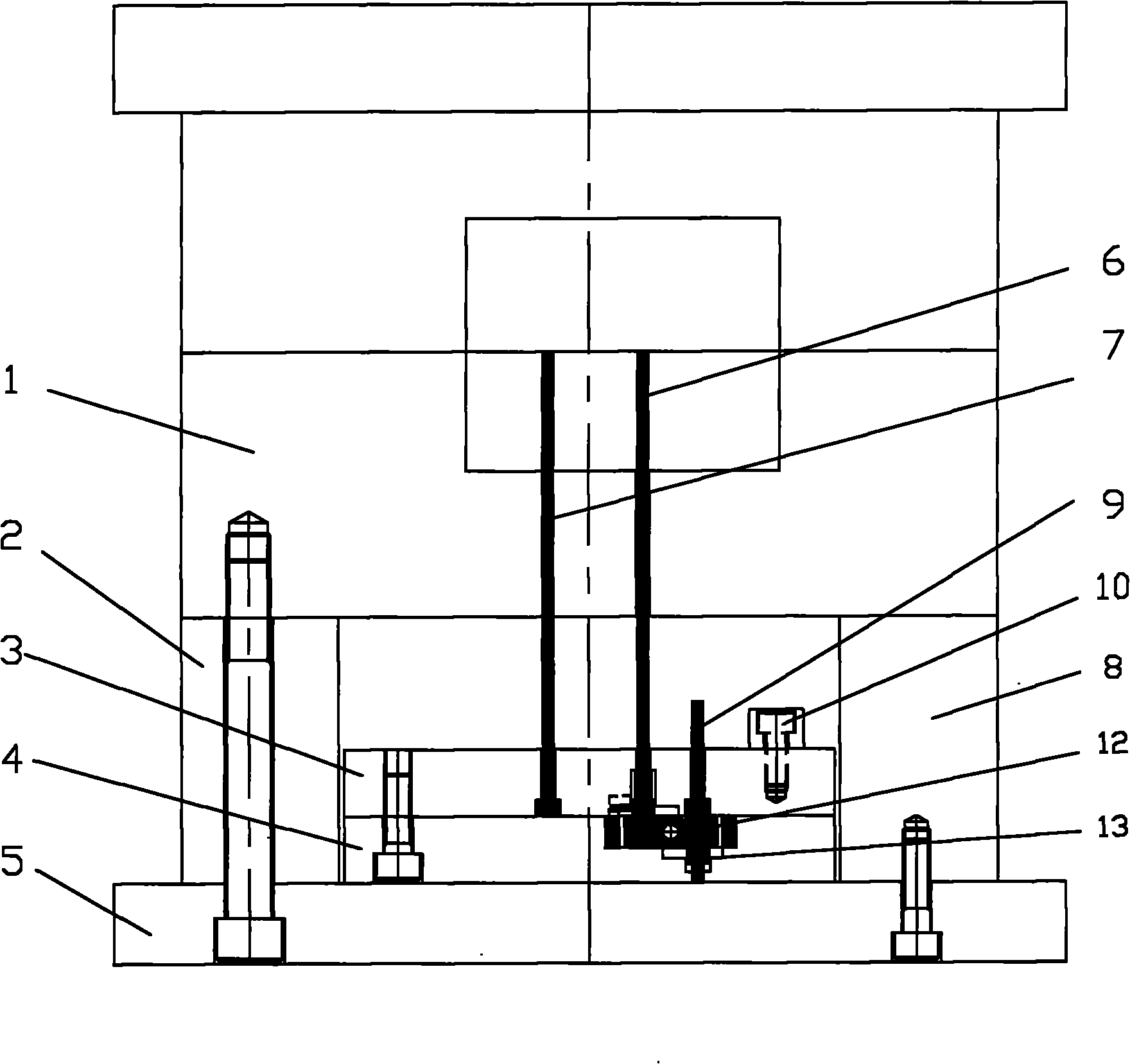
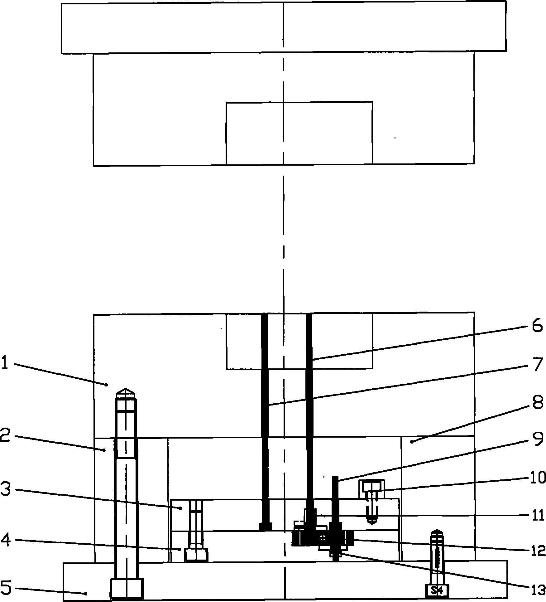
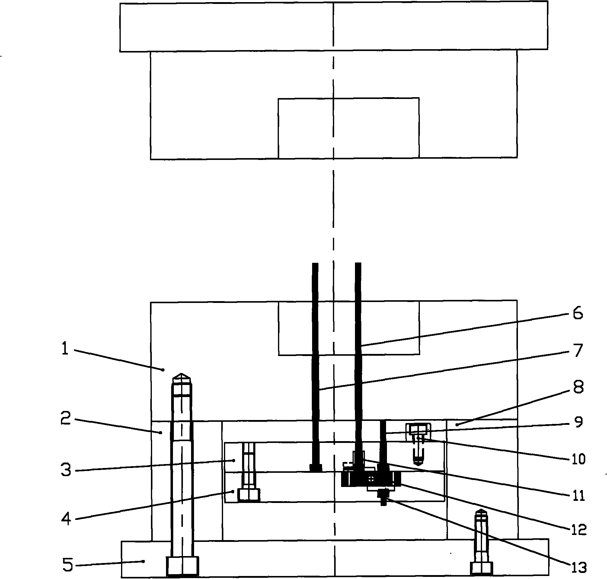
[0016] The lower ejector plate 4 slidably arranged between the movable mold body plate 1 and the rear plate 5, and the upper ejector plate 3 fixedly arranged above the lower ejector plate 4, the injection mold includes a fixed The left pillow board 2 and the right pillow board 8 between the movable mold body board 1 and the rear board 5, the upper ejector board 3 and the lower ejector board 4 are arranged on the left pillow board 2 and the right pillow board 8, the upper ejector plate 3 or the lower ejector plate 4 can slide up and down relative to the rear plate 5 driven by the driving parts. figure 1 Corresponds to the upper and lower positional relationships shown in .

[0017] The upper ejector plate 3 is fixedly provided with a first-stage ejector 7 and a limit block 10, and the upper ej...


PUM


Abstract

The invention discloses an ejection mechanism for an injection mould. The ejection mechanism comprises a lower ejection plate and an upper ejection plate which are slidably arranged between a movable mould body plate and a rear plate, a first-level ejection member, a second-level ejection member slidably arranged on the upper ejection plate, and a rocking plate, wherein the lower ejection plate is provided with an accommodating groove for accommodating the rocking plate, and the upper ejection plate is provided with a limiting block and a second-level braking block; the second-level ejection member and the second-level braking block are respectively positioned on the two sides of the rotation axis of the rocking plate; when the rocking plate is at a first working position, an upper end part of the second-level braking block is higher than the limiting block, and the first-level ejection member is flush with the upper end part of the second-level ejection member; when the rocking plate is at a second working position, the upper end part of the second-level braking block is flush with the limiting block, a lower end part of the second-level braking block stretches into the accommodating groove and is pressed against one end part of the rocking plate, the other end part of the rocking plate is pressed against the lower end part of the second-level ejection member, and the upper end part of the second-level ejection member is higher than the first-level ejection member. The ejection mechanism can finish two-level ejection at the same time and improve the demoulding efficiency.

Description

technical field [0001] The invention relates to an ejection mechanism of an injection mold. Background technique [0002] In the processing and manufacturing of plastic parts, for plastic parts with complex shapes, due to the complex mold surface structure, the demoulding resistance is relatively large, and it is difficult to take out. If a one-time push-out mechanism is used, it is easy to cause deformation and damage to the plastic parts, so it is necessary to design a second push-out mechanism, and the secondary ejection mechanism of the injection mold in the prior art usually requires two driving parts to drive the two-stage ejectors to move step by step, which is not only complicated to control, but also takes a long time to operate, and the efficiency of large-scale production is not high . Contents of the invention [0003] The purpose of the present invention is to provide an ejection mechanism capable of realizing rapid ejection of plastic parts. [0004] In ord...

Claims


Application Information

Patent Timeline
Patent Type & Authority Applications(China)
IPC IPC(8): B29C45/40
Inventor 陈潮
Owner SHENGMEI PRECISION INDAL KUSN
Why Eureka
Try Eureka