
Locking device capable of maintaining three positions of handle for low-voltage circuit breaker and method thereof

A low-voltage circuit breaker and locking device technology, applied in circuits, protection switch operation/release mechanisms, electrical components, etc., can solve problems such as misoperation, inability to achieve multi-person control, and inability to use locking devices to ensure safety and reliability. , Reliable locking effect and simple structure

Active Publication Date: 2010-11-10
伊顿辉能低压电器(江苏)有限公司
View PDF6 Cites 5 Cited by
  • Summary
  • Abstract
  • Description
  • Claims
  • Application Information

AI Technical Summary

Problems solved by technology

[0003] At present, in order to realize the function of maintaining the position of the handle of the circuit breaker, a padlock is often used to lock the handle. Before changing the position of the circuit breaker, the padlock must be released first, and then the handle is operated. The disadvantages are: Lock the padlock on one or two positions of the circuit breaker. When locking three different positions, the locking device cannot be used universally.
2. Using a padlock is easy to cause misoperation and cannot realize multi-person control

Method used


Image

  • Locking device capable of maintaining three positions of handle for low-voltage circuit breaker and method thereof
  • Locking device capable of maintaining three positions of handle for low-voltage circuit breaker and method thereof
  • Locking device capable of maintaining three positions of handle for low-voltage circuit breaker and method thereof

Examples


Embodiment Construction

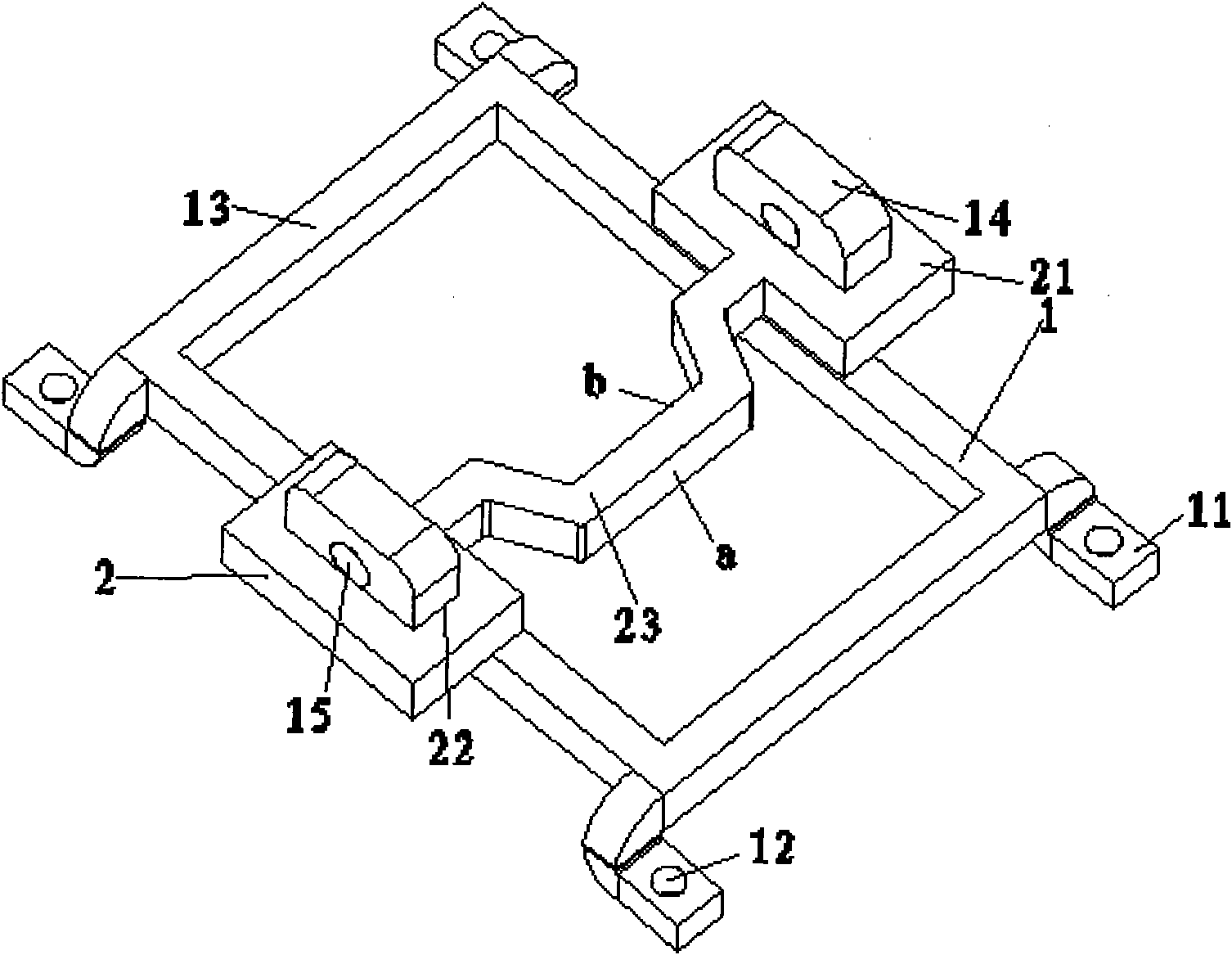
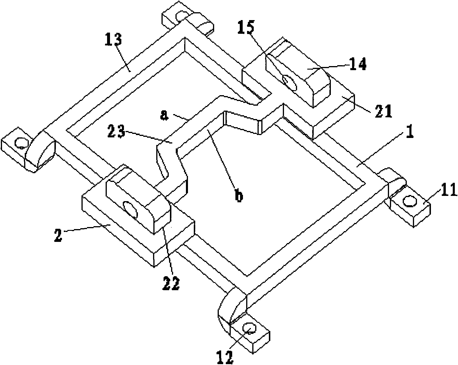
[0020] Such as Figure 1-2 As shown, the locking device of the present invention is composed of two parts, the support 1 and the catch 2 . The support 1 and the blocking piece 2 are made of metal materials by bending and other forming processes.

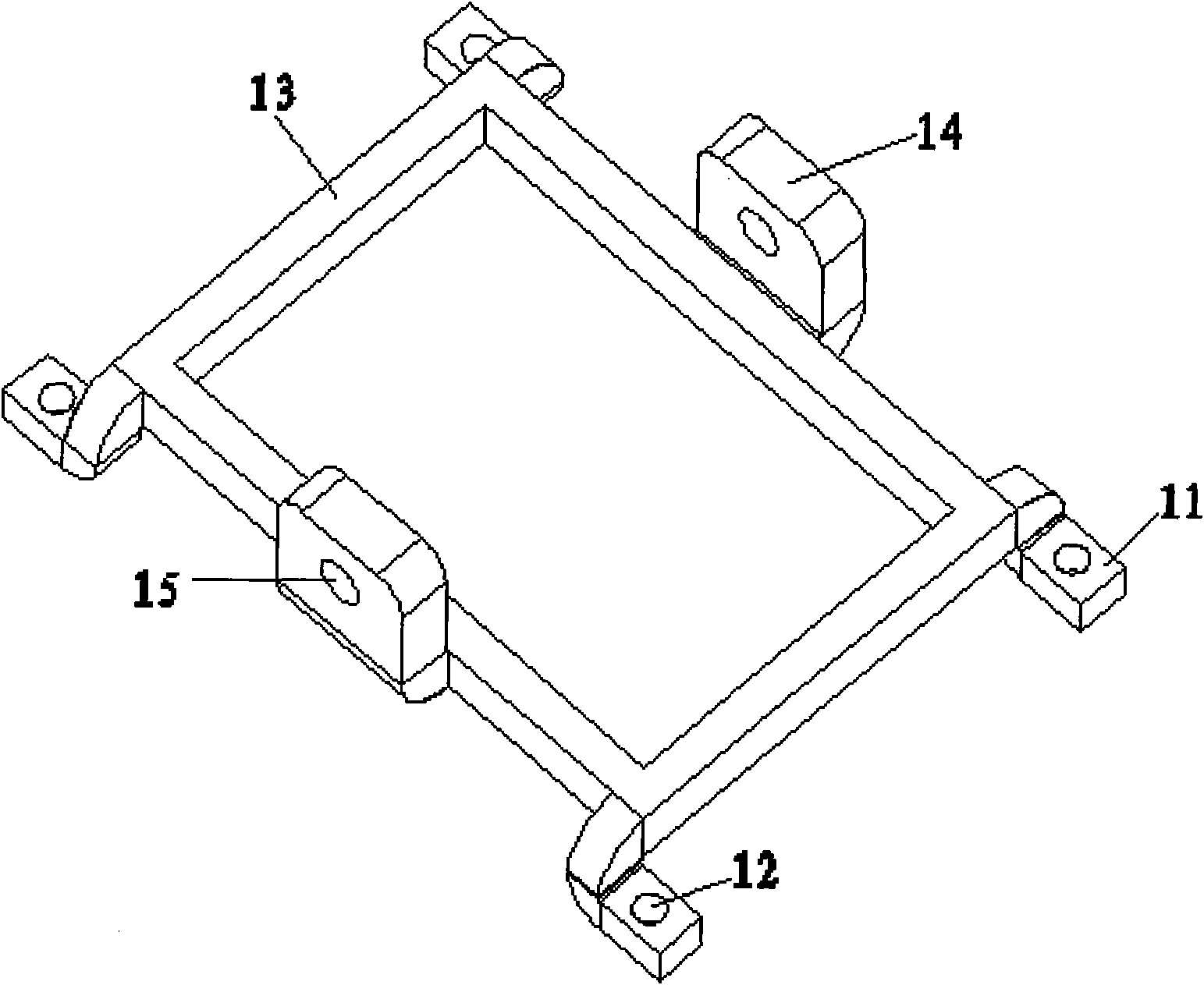
[0021] Such as image 3 As shown, the support 1 has a support body 13, the support body 13 is a square frame structure, and a mounting foot 11 is respectively fixedly connected to the horizontal direction of the four corners of the support body 13 square frame, and the bottom surface of the mounting foot 11 is flat with the bottom surface of the support body 13. together. A positioning hole 12 is vertically provided on each mounting foot 11 . A positioning platform 14 is respectively fixedly connected to opposite side frames of the supporting body 13 , and the positioning platform 14 protrudes upwards in the vertical direction of the supporting body 13 , and a locking hole 15 is horizontally arranged on the positioning platform 14...


PUM


Abstract

The invention discloses a locking device capable of maintaining the three positions of a handle for a low-voltage circuit breaker and a method thereof. The locking device comprises a support and a retainer, wherein the retainer is formed by connecting two supporting parts and a locking part; a convex surface and a concave surface corresponding to the convex surface are arranged right in the middle of the locking part; a positioning groove and a positioning platform in clearance fit are arranged on the supporting parts; the support is fixed on the top cover of the circuit breaker, and the handle of the circuit breaker in the switching-on position extends upwards out of the support, so the handle of the circuit breaker can be locked in different positions by changing the placement of the retainer, wherein the placement direction of the retainer in the switching-off position is the same as that of the retainer in the trip-free position, while the acting surface of the retainer in the switching-off position is different from that of the retainer in the trip-free position, and the placement direction of the retainer in the switching-on position is opposite to the placement directions of the retainer in the switching-off and trip-free positions; and two padlocks are respectively inserted into two padlock holes of the support and further locked. Accordingly, the handle of the circuit breaker has universality and reliable locking-up effect in the switching-on, switching-off and trip-free positions, thus achieving the multi-user and multi-lock control.

Description

technical field [0001] The invention relates to the technical field of low-voltage circuit breakers, in particular to a locking device for a handle that performs power-on and power-off actions of the low-voltage circuit breaker. Background technique [0002] At present, the molded case low-voltage circuit breaker is opened and closed through the handle to realize the power-on and power-off functions of the circuit breaker. When the circuit breaker is in use, it has three different positions: opening, closing and free tripping. The function of the circuit breaker handle is to keep the circuit breaker in its position reliably. In order to prevent the circuit breaker handle from being accidentally misoperated, affecting the power on and off, or affecting the safety of maintenance personnel during maintenance, it is particularly important to keep the position of the circuit breaker handle from being changed so that it will not be misoperated. . [0003] At present, in order to...

Claims


Application Information

Patent Timeline
IPC IPC(8): H01H71/10H01H71/50H01H9/28
Inventor 张海燕杨怀亮郑改红
Owner 伊顿辉能低压电器(江苏)有限公司
Learn More