Vehicle-carrying tray

A technology of car tray and parking space board, which is applied in the direction of parking buildings, building types, supporting machines, etc. It can solve the problems of parking space boards without guide beams and large spans of parking space boards, so as to save raw materials and improve carrying capacity , to avoid the effect of direction deviation

Active Publication Date: 2010-11-17
朱建华
View PDF5 Cites 10 Cited by
  • Summary
  • Abstract
  • Description
  • Claims
  • Application Information

AI Technical Summary

Problems solved by technology

The above-mentioned patent uses C-shaped steel as the raw material for the parking space board (composed of a plurality of parallel beams), although the weight of the parking space board can be reduced to a certain extent, the parking space board still adopts an integral structure, that is, each cross beam The two ends are fixedly connected to the side beams on both sides of the platform. The span of the parking space is still relatively large. In order to ensure the bearing weight, the parking space cannot be made too thin. Moreover, there is no guide beam on the parking space. When the parked vehicle drives When entering the parking space of the three-dimensional garage, the vehicle is easy to deviate from the middle straight line, causing the vehicle to be parked obliquely on the car tray, which brings a lot of inconvenience when the vehicle leaves the car tray

Method used


Image

  • Vehicle-carrying tray
  • Vehicle-carrying tray
  • Vehicle-carrying tray

Examples


Embodiment Construction

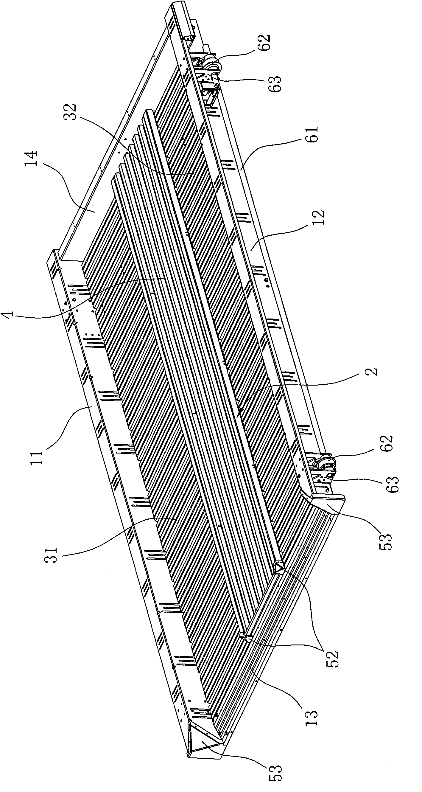
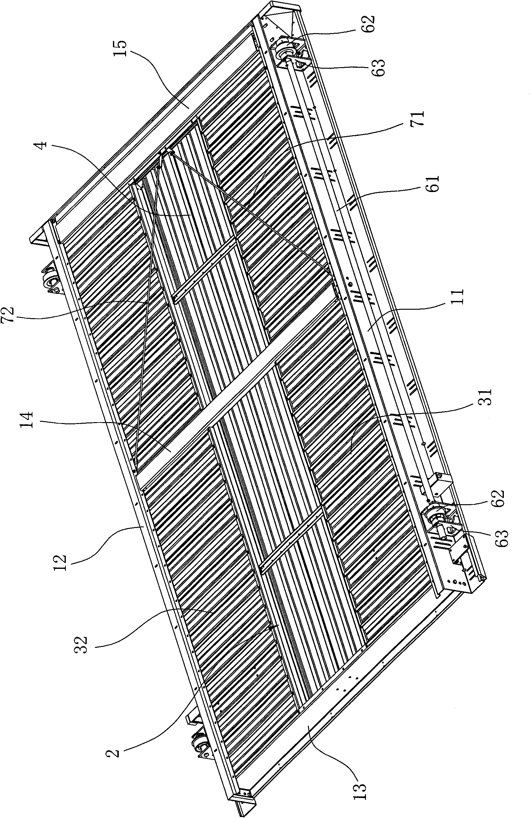
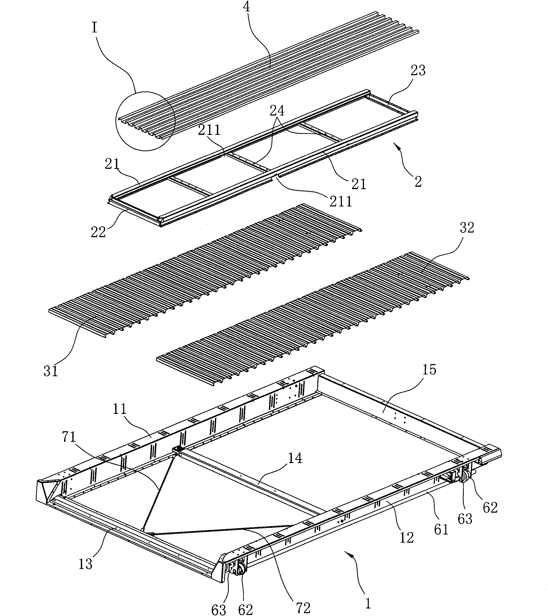
[0020] The present invention will be further described in detail below in conjunction with the accompanying drawings and embodiments.

[0021] Such as Figure 1 to Figure 6 As shown, it is a specific embodiment of the present invention. The car-carrying tray of this embodiment includes a bottom frame 1, and the bottom frame 1 is composed of a left side beam 11, a right side beam 12 arranged parallel to each other, and a left side beam 11 and a right side beam 12. Composed of beams between them, the beams include front beams 13, middle beams 14 and rear beams 15, wherein the front of the front beams 13 is inclined to form a slope, when the vehicle is driven into the car tray, it can be driven into and Drive out, make the entry and exit of vehicle more stable, the two ends of front beam 13 are respectively fixedly connected to the front ends of left beam 11 and right beam 12, and the two ends of rear beam 15 are respectively fixedly connected to the rear end of left beam 11 and ...


PUM


Abstract

The invention discloses a vehicle-carrying tray, which comprises a bottom frame consisting of a left edge beam and a right edge beam which are parallelly arranged and cross beams arranged between the left edge beam and a right edge beam. The vehicle-carrying tray is characterized in that: the vehicle-carrying tray also comprises an auxiliary frame which is positioned at the central position of the bottom frame and is respectively parallel to the left edge beam and the right edge beam; a first parking plate is paved between the auxiliary frame and the left edge beam, and a second parking plate is paved between the auxiliary frame and the right edge beam; one end of the first parking plate is vertically fixed with the left edge beam; the other end of the first parking plate and the auxiliary frame are vertically fixed relative to a side edge arranged on one side of the left edge beam; one end of the second parking plate is vertically fixed with the right edge beam; and the other end of the second parking plate and the auxiliary frame are vertically fixed relative to a side edge arranged on one side of the right edge beam. Compared with the prior art, the vehicle-carrying tray has the advantages that: the bottom frame of the vehicle-carrying tray is provided with the auxiliary frame, and the parking plates have small span and need thinner materials, so the raw materials are obviously saved and the cost is reduced; and the vehicle-carrying tray can also avoid direction shift in the process that a vehicle pulls in, and ensures that the vehicle parks at a correct position.

Description

technical field [0001] The invention relates to a car tray for a three-dimensional garage. The tray can be used not only as a laterally moving tray, but also as a lifting tray. Background technique [0002] Most of the car-carrying disc structures of existing three-dimensional parking garages are frame structures, which generally consist of left beams, right beams, and crosspieces arranged between the left beams and right beams, and the frame structure is formed between the left beams and the right beams. There is also an integral parking space board arranged horizontally in the room, and the vehicle is parked on the parking space board. However, the disadvantage of the existing vehicle-loading plate structure is that the parking space plate for parking vehicles is straddled between the left beam and the right beam. Steel plate production, many consumables, high cost. [0003] In order to solve the problem that the parking space board is too thick, the existing patent No. ...

Claims


Application Information

Patent Timeline
Patent Type & Authority Applications(China)
IPC IPC(8): E04H6/12
CPCE04H6/225F16M11/20E04H6/00
Inventor 朱建华
Owner 朱建华
Why Eureka
Try Eureka