Wood stove radon reduction system

A firewood and radon technology, applied in the field of firewood stoves, can solve the problems of increasing production costs and maintenance

Inactive Publication Date: 2010-11-17
乔治・基尔默
View PDF9 Cites 1 Cited by
  • Summary
  • Abstract
  • Description
  • Claims
  • Application Information

AI Technical Summary

Problems solved by technology

The need for a blower not only increases the production cost

Method used


Image

  • Wood stove radon reduction system
  • Wood stove radon reduction system
  • Wood stove radon reduction system

Examples


Embodiment Construction

[0023] To promote an understanding of the principles of the invention, reference will now be made to the embodiments illustrated in the drawings and specific language will be used to describe the same. It will however be understood that no limitation on the scope of the invention is thereby intended, and that certain adaptations and further modifications in the apparatus shown, as well as certain further applications of the principles of the invention as described herein are to be understood as It would normally occur to those skilled in the art to which the present invention pertains.

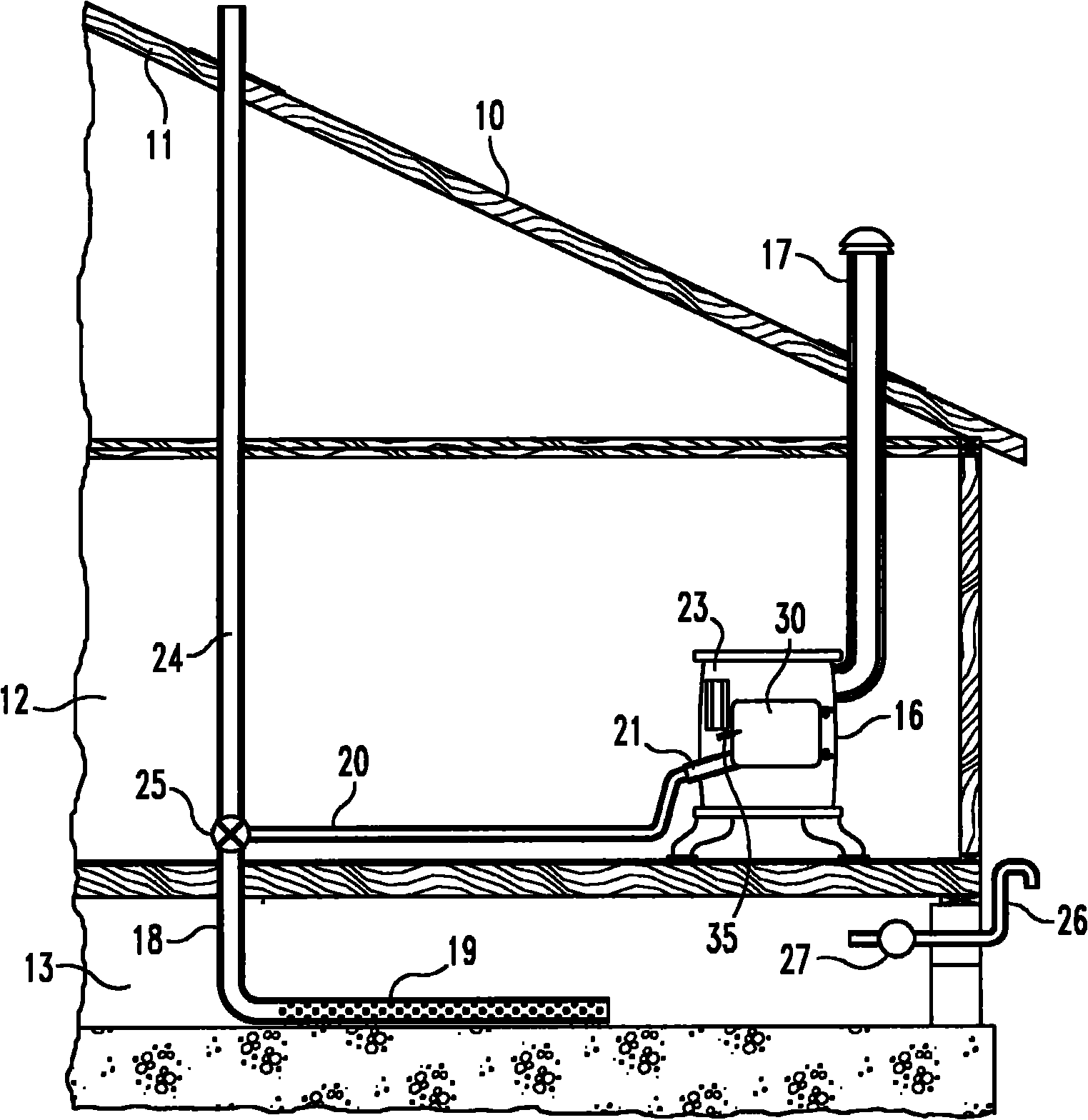
[0024] See now more specifically figure 1 , partially shows a building 10 having a roof 11 , an interior room 12 and a basement 13 . A wood stove 16 is located in the room 12 and has a conventional outlet flue 17 extending through the roof 11 to allow exhaust gases from the stove to escape the building. A radon collection system 18 is provided to collect radon gas from the basement through a...


PUM


Abstract

A combination of a wood stove and radon collecting system. A radon collection tube located in the basement of a building is connected via conduit leading into the combustion chamber of the stove. Burning wood within the combustion chamber is operable to normally cause radon within the building to flow into the radon collection tube, through the combustion chamber and then out through an exhaust tube. In the absence of burning wood, a lighted candle is placed in the combustion chamber tube to cause the radon within the radon collection tube to flow into the combustion chamber and then out through the exhaust tube.

Description

[0001] Cross References to Related Applications [0002] This application is a continuation-in-part of application serial number 11 / 423180 filed June 9, 2006, which is incorporated herein by reference. technical field [0003] The present invention relates generally to the field of wood stoves. Background technique [0004] In some areas of the countryside, radon collects in the basements of buildings. Typically, a blower connected to a collection pipe extending outward from the building is operable to force the radon gas away from the building. The collecting pipe can extend into the basement or under the basement or into the building slab. The need for a blower not only adds to the production costs of the system but also requires maintenance and electricity. What is needed is a radon collection system that will use the heat within the heating system to force the radon out of the building. Also, there is a need to combine the system eg with a wood stove or candle burnin...

Claims


Application Information

Patent Timeline
IPC IPC(8): F23G7/06
Inventor 乔治·基尔默
Owner 乔治・基尔默
Why Eureka
Try Eureka