Metal shell and electric connector using same

A metal shell and electrical connector technology, applied in the direction of connection, connection component installation, connection device components, etc., can solve the problems of wasteful production cost and reduction of metal plates, and achieve the effect of rational design and reduction of manufacturing cost.

Active Publication Date: 2010-11-17
FUDING PRECISION IND ZHENGZHOU CO LTD +1
View PDF3 Cites 2 Cited by
  • Summary
  • Abstract
  • Description
  • Claims
  • Application Information

AI Technical Summary

Problems solved by technology

Since the welding feet extend from the rear wall, the metal sheets parallel to the rear wall on both sides of the welding feet need to be knocked off, which causes waste of metal sheets and is not conducive to the reduction of production costs

Method used


Image

  • Metal shell and electric connector using same
  • Metal shell and electric connector using same
  • Metal shell and electric connector using same

Examples


Embodiment Construction

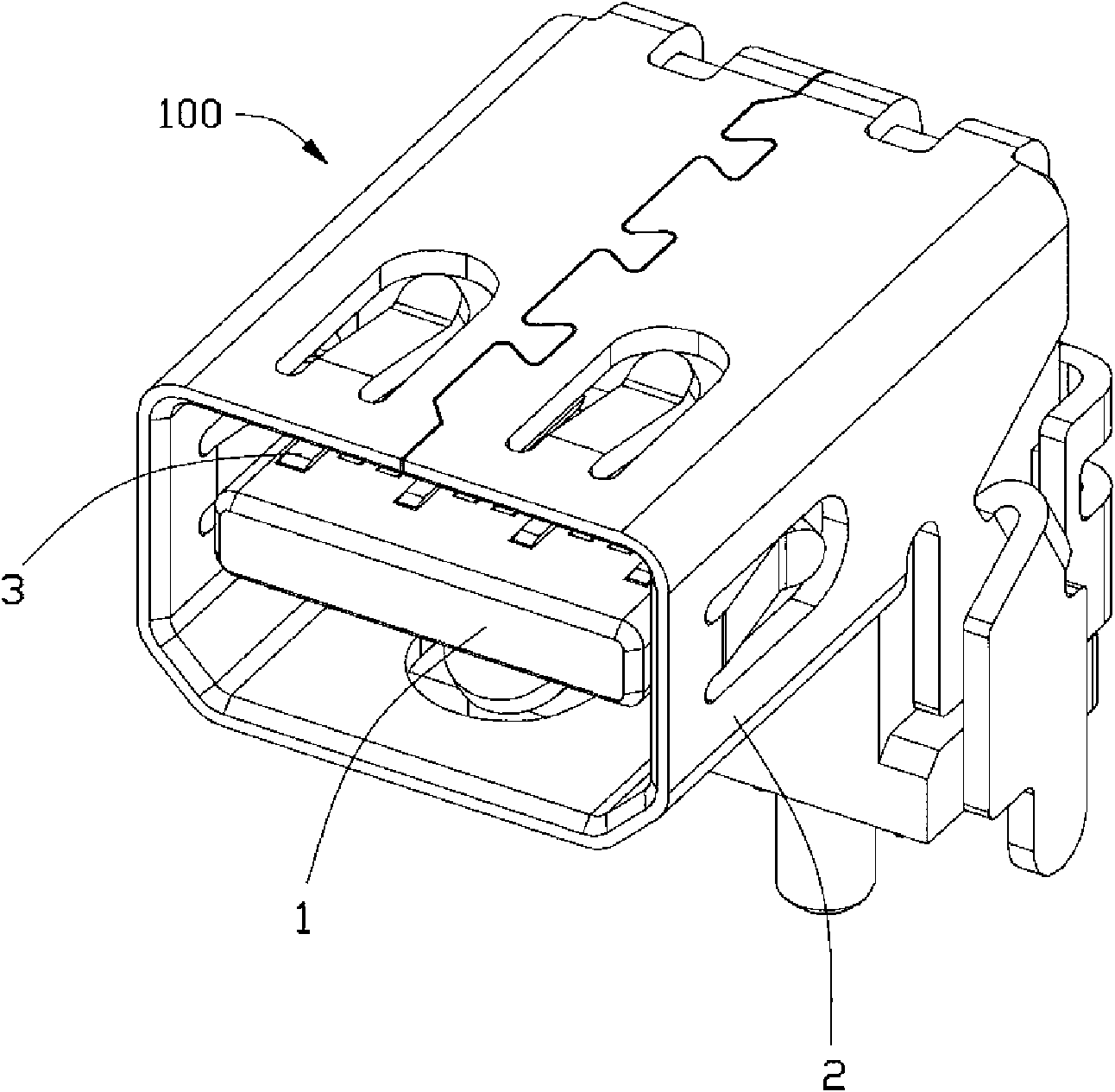
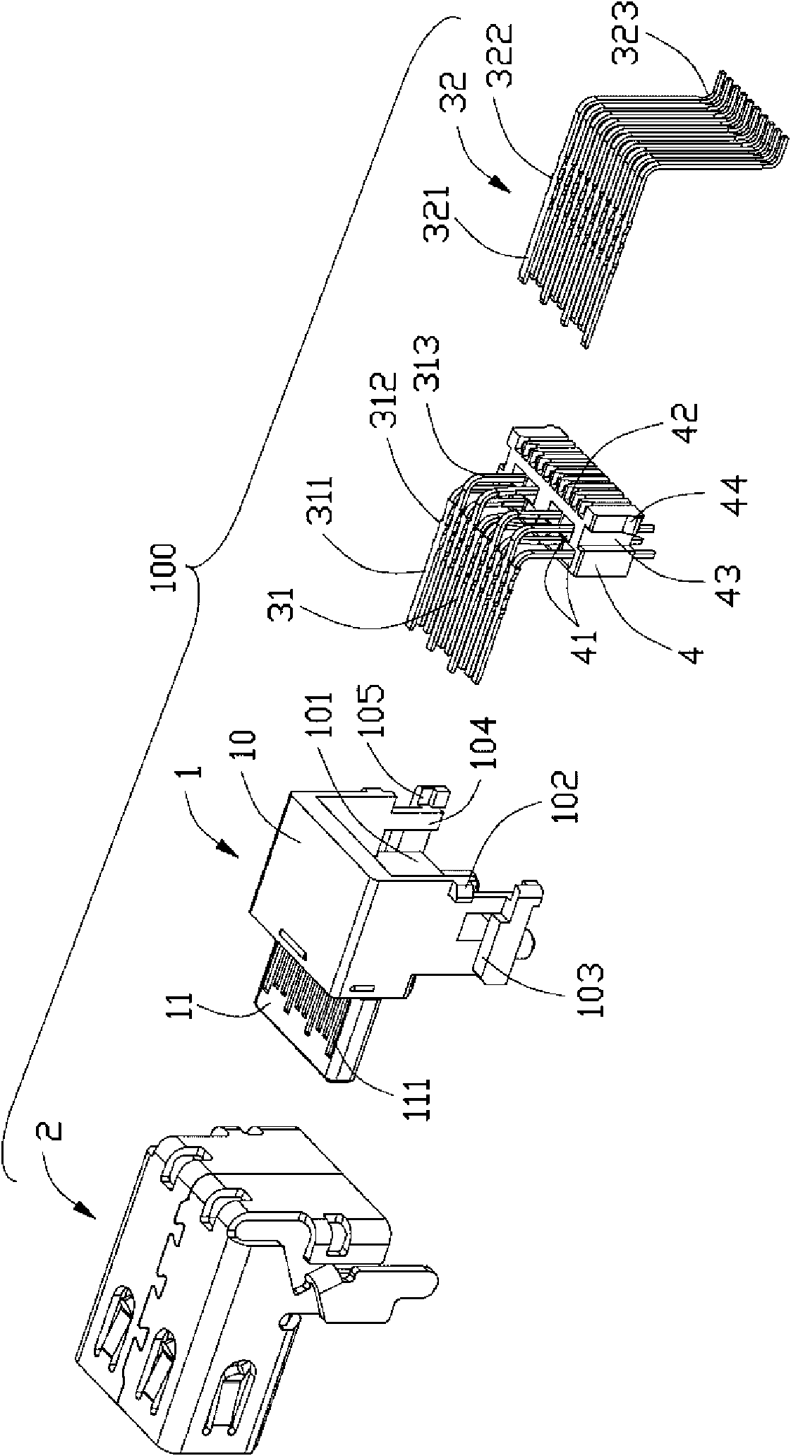
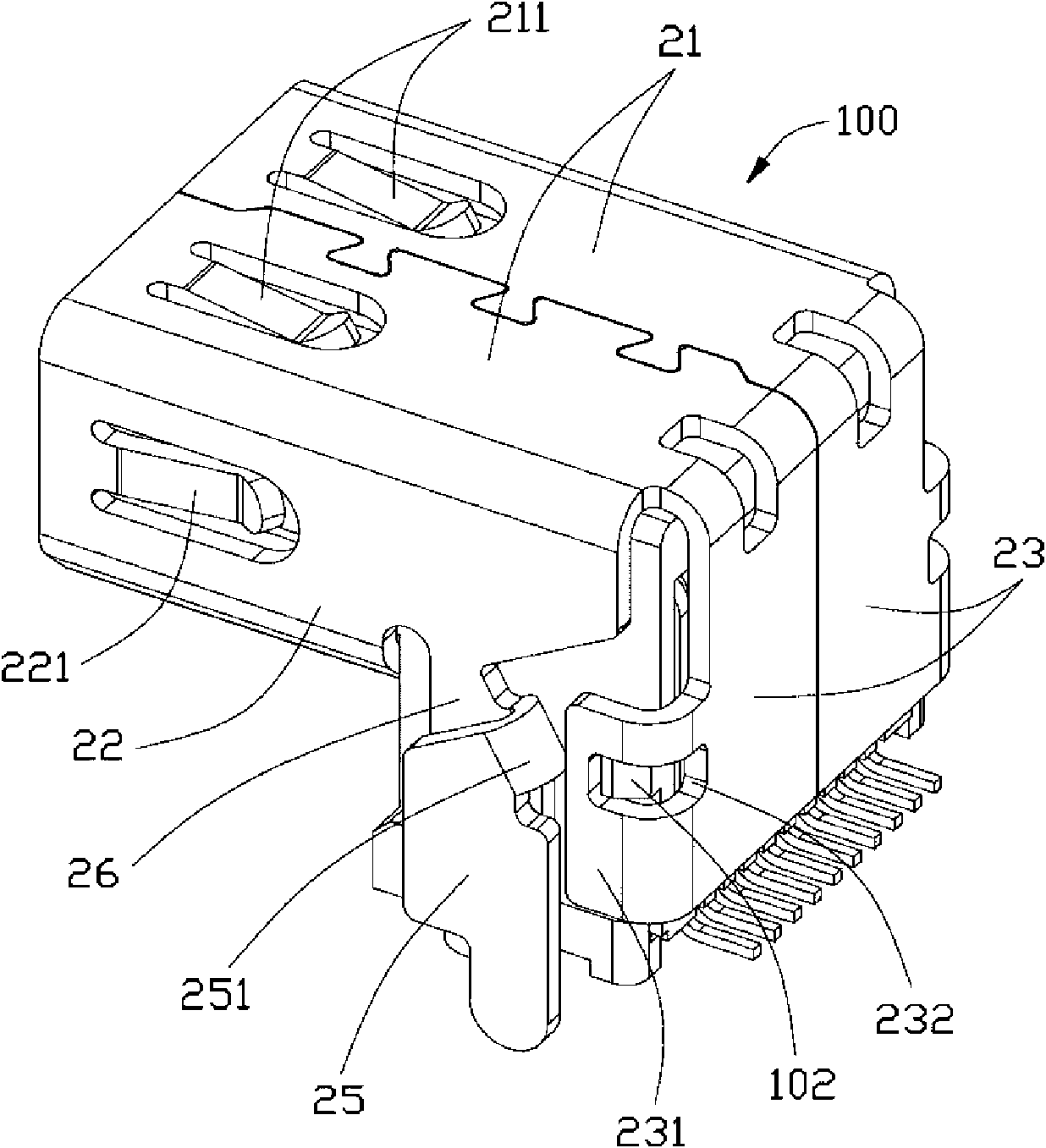
[0014] Such as figure 1 As shown, the electrical connector 100 of the present invention includes an insulating body 1 , a terminal group 3 fixed in the insulating body 1 , and a metal shell 2 covering the insulating body.

[0015] Such as figure 2 As shown, the insulating body 1 includes a rectangular body portion 10 and a tongue portion 11 vertically extending forward from the body portion 10 . The upper and lower surfaces of the tongue portion 11 are respectively provided with a plurality of terminal slots 111 at intervals, and the terminal slots pass through the body portion 10 of the insulating body backward to facilitate the insertion of the terminal group 3 into the terminal slots 111 from back to front. The rear part of the main body 10 is depressed inwardly to form a receiving cavity 101, and a vertical rib 104 and a protrusion 105 located at the rear end of the rib 104 are respectively provided on both sides of the receiving cavity, and the upper part of the protrus...


PUM


Abstract

The invention discloses an electric connector, comprising an insulation body, a plurality of terminals and a metal shell, wherein the insulation body comprises a main body part and a hyoplastron part extending forward from the main body part; each terminal comprises a contact part contained in the hyoplaston part and a welding part extending out of the main body part; the metal shell is integrated into a whole and comprises a chamber and a rear wall, wherein the hyoplaston part of the insulation body is contained in the chamber, the rear wall is arranged at one end of the chamber, and the chamber is provided with an front opening; and the metal shell is buckled in opposite direction at the position at which the chamber is near to the rear wall to form a weld leg, so as to fully utilize the limited space of the metal material and reduce production cost.

Description

【Technical field】 [0001] The invention relates to an electrical connector, in particular to an electrical connector with a metal shell. 【Background technique】 [0002] Chinese Invention Patent No. 98108747.7 discloses an electrical connector, which includes an insulating body and a metal shell fixed outside the insulating body. The metal casing is formed by stamping, bending and snapping a metal plate, and includes an upper wall, a lower wall, a left side wall, a right side wall and a hollow cavity for accommodating an insulating body surrounded by the aforementioned walls. The rear end of the cavity is provided with a rear wall that is bent downward from the upper wall, and the rear wall is bent to both sides to form an extension piece, and the opening provided on the extension piece is buckled with the corresponding protrusion of the insulating body to form a closed metal casing. The end of the extension piece also extends downwards to form a soldering foot protruding fr...

Claims


Application Information

Patent Timeline
Patent Type & Authority Applications(China)
IPC IPC(8): H01R12/14H01R13/516H01R13/73H01R12/16
Inventor 林旻翰徐国峻
Owner FUDING PRECISION IND ZHENGZHOU CO LTD
Why Eureka
Try Eureka